MES SQA-Vision Service Manual Download Page 16

SQA-Vision 

Service Manual Version 109.13.4      


Edition rev.: Jan 2020 

                    16 


SECTION 1: 

SN #5228 

and below


WARNING: 
The two ends of 
the Data flat cable 
must be connected 
in the same way at 
each of the nodes 
(Operation 
monitor, 
Motherboard) or 
the LCD may be 
burned! 


ISSUE #2- Blank Screen:


There is no data displayed on the screen although the SQA-Vision is ON, both power indicators 
are functioning and the fan is working. 

PLEASE NOTE: The instructions depend on the SERIAL NUMBER (SN#) of the SQA-V.  


SN# 5228 and below – follow the instructions in SECTION 1 


SN# 5229 and above – follow the instructions in SECTION 2 


Re-install SQA-Vision software. 


If the software was not installed successfully- please refer to the technical bulletin in the 
appendix section for further instructions 


If the software was installed successfully and the problem remains- check the Data flat 
cable: 


Open the SQA-Vision and verify that the Data flat cable, with the red lined side up is 
connected to the section designated with a 12 on the main board 


Replace the flat cable if it appears damaged in any way. 


If replacing the cable does not work- replace the processor on the main board (see 
Appendix section for instructions).  


If replacing the processor does not work: 


Re-start the SQA-Vision and see if the LCD Operation Monitor is still blank.  If yes, replace 
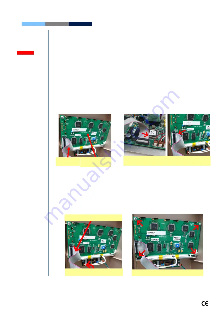
the screen: 


Disconnect the Operation Monitor Data and Backlight lamp cable 


Unscrew the four screws. 


Replace the screen & reconnect the Data and Backlight lamp cables. 


In case the problem persists after replacing the LCD screen- contact MES Customer 
Support. 


Unscrew the


four screws


Note the alignment of the 

red

 line on the Data 

cables 

Backlight lamp cable 

Data Cable 

Data Cable 

LCD Operation 

Monitor/Board 

Summary of Contents for SQA-Vision

Page 1: ...V e r s i o n 1 0 9 1 3 4 C a t a l o g V S M L 0 1 0 9 1 0 0 R e v J a n 2 0 2 0...

Page 2: ...on Start Up 9 Prior to testing a sample 10 SECTION VI Getting Started Set Up Getting Started Set Up 10 SECTION VII Troubleshooting Overview 11 SECTION VIII Technical Support and Part Replacement Instr...

Page 3: ...nt is performed using the DEBRIS ROUND CELLS SCANNER Normal morphologically is assessed automatically along with other semen parameters Vitality and Morphology differentials can be assessed manually u...

Page 4: ...lgorithm makes an adjustment to account for the infrared light absorption of the seminal fluid components SQA Vision Reportable Range Automated Results Sample Type Sperm Conc M ml Motility Morph MSC M...

Page 5: ...fuses 250V 2A RS232 connector 2 USB 2 0 B Type Male On Off switch of the blue surrounding LEDs located on bottom side of the panel Left Side Panel Power On Off switch I Button port Visualization Comp...

Page 6: ...e known effect of temperature on human semen Operational Environmental conditions System is intended for indoor use at a maximum altitude of 2000m mains supply fluctuations 10 Overvoltage Category II...

Page 7: ...to move to the next screen or field Use the ESC button to return to the previous screen or field Rear Panel Rear Panel Operation Display I Button Keypad Automated Measurement Compartment Focus Knob F...

Page 8: ...rtment Measurement Compartment Focus Control Field of View control Motherboard Schematic Schematic of the SQA Vision Motherboard 5 VDC 3 VDC 12 VDC 2 VDC AC 100 230 V 50 60 Hz 12 VDC 5 VDC 12 VDC 12 V...

Page 9: ...Accessories Kit Each kit contains Power Cables Communication Cable USB cables RS232 cable RS232 to USB converter Instructional Guides Slide holder Additional set of device feet Barcode reader Capillar...

Page 10: ...verification Reference parameters of the concentration and motility channels are measured again without a testing capillary System noise Measures the electronic noise level of the system to insure eff...

Page 11: ...y cause damage to the calibration AND will VOID THE WARRANTY The electro optical board should NEVER be touched when the SQA Vision is opened it will cause damage to the system s calibration Technical...

Page 12: ...lly peel off the damaged keypad from the front panel Clean the surface with alcohol and let it dry Pull the keypad cable through slit in the front panel Please note DO NOT connect it currently Attach...

Page 13: ...ltage is evident replace the power inlet see the relevant section below If voltage is being supplied to the input connector check the output connector How to check the output voltage of PSU Disconnect...

Page 14: ...pull the power inlet out of the SQA Vision through the rear panel Insert a new power inlet and re connect the cables Re connect the internal cables re place the internal cover and re connect the power...

Page 15: ...re the old inverter board Replace the inverter board with a new one and secure it with the two screws Re connect the cables of the inverter board If the problem persists contact MES Customer Support S...

Page 16: ...ns If the software was installed successfully and the problem remains check the Data flat cable Open the SQA Vision and verify that the Data flat cable with the red lined side up is connected to the s...

Page 17: ...able which connects the main board and the Backlight PCB Item KHD 908 000858 If replacing the long flat cable does not work Replace the short flat cable which connects the LCD screen and the Backlight...

Page 18: ...b Part VS M 01105 00 ISSUE When using the FOV knob there is no change in the field of view SOLUTIONS This is described in a separate technical bulletin please contact MES support services for further...

Page 19: ...02 Issue When the SQA Vision is turned on it fails SELF TEST Ensure there is no testing capillary in the measurement compartment Remove the SQA Vision from sources of electronic noise cell phones etc...

Page 20: ...ector from its location on the main board J13 Attach a new capillary sensor to the optical block using a screw Gently re attach the Dust Buster to the Optical Block using the 4 Phillips screws Re atta...

Page 21: ...connect the optical assembly from the front panel by unscrewing 5 screws using a 2 5 Allen Key Release the screws at the rear section of the optical column using a 2 5 Allen key Release the zoom DC mo...

Page 22: ...a assembly Slide the entire new camera assembly back into the optical assembly over the false track Re attach the Camera Stopper Reassemble the optical assembly by screwing the four screws on the rear...

Page 23: ...SQA Vision by unscrewing the screws from the rear panel using a 2 Philips screwdriver Pull out the focus knob Using a 2 5 Allen Key release the 5 screws which hold the Optical column to the front pan...

Page 24: ...SQA Vision Service Manual Version 109 13 4 Edition rev Jan 2020 24 SECTION IX Appendixes Appendix 1 SQA Cleaning Instructions...

Page 25: ...t it into the correct position 4 Close the SQA Vision and tighten all screws of the rear panel 5 Connect the power cable of the SQA Vision 6 Turn the SQA Vision on and run the SELF TEST 7 If the SQA V...

Page 26: ...e processor socket see the figure to the right 5 Slightly press the center of the processor with an index finger to re seat it into the correct position see the figure to the right 6 Close the SQA Vis...

Page 27: ...K Problem was solved Yes Yes Yes Yes End of troubleshooting Not Not Not Not Voltage is OK Check the input voltage of PSU see p 13 Not OK Not OK Not OK Not OK Replace the power inlet see p 14 OK OK OK...

Page 28: ...LF TEST If the LED CURRENT 1 LED 1 is not within the acceptable range of 5 20mA and is not identical to the initial manufacturer s setting you must compare it indicates the following High vs Initial S...

Page 29: ...500mV 3 500mV C O N C E N T R A T I O N REFERENCE 2 REF 2 2500 3500 REFERENCE 2 FAILED THE SELF TEST If the REFERENCE 2 REF 2 is not within the acceptable range of 2500 3500mV it indicates the followi...

Page 30: ...negative control is within the acceptable range as specified on the controls box Control Level 1 2 3 negative CONTROL LEVEL TEST STATUS IS NOT DEFINED If there is a probability that the control test...

Page 31: ...ESSQAV mdf file is closed properly Call for technical assistance if the problem remains Last Backup BACKUP DESCRIPTION FILE WAS NOT SAVED THIS ERROR DOES NOT CAUSE THE BACKUP PROCESS TO FAIL SO YOU MA...

Reviews: