Meritor RS-220 Maintenance Manual Download Page 38

Section 5
Assembly 

34

18. Check and write down the number engraved 

on the end of the pinion. This value indicates 
how many hundredths of a millimeter have to 
be added or subtracted from the corrected 
nominal dimension. 

Figure 5.30

.

19. Subtract the corrected specific nominal 

dimension (Csnd) from the differential 
nominal dimension maximum value (Mv).

The result will be the thickness of the shim 
pack(s) to be added to obtain proper drive 
pinion/ring gear tooth contact.

Csnd = SND – engraved number

Shim pack thickness = Mv – Csnd

Example:

The following are the values for a 220 differential:

1.

Differential nominal dimension maximum 
value (Mv) is determined using a special tool:

Mv = 200.70

2.

Number engraved on the top of the drive 
pinion:

– .06

3.

Specific nominal dimension (SND) of this 
differential model:

SND = 200.00

From these values we can determine the corrected 
specific nominal dimension (Csnd):

Number –6 engraved on the end of the drive 
pinion signifies that the variation in the height of 
the pinion in relation to the differential nominal 
dimension is 0.06 mm lower than the specific 
nominal dimension (SND), so: 

SND – engraved number = Csnd

200.00 – 0.06 = 199.94

Therefore, 199.94 is the corrected specific nominal 
dimension (Csnd) for the differential.

To determine the thickness of the shim pack(s) 
needed to obtain a proper drive pinion/ring gear 
tooth contact, we subtract Csnd (corrected specific 
nominal dimension) from Mv (maximum value).

Mv – Csnd = Thickness of the shim pack 

200.70 – 199.94 = 0.76 mm

We therefore have to insert 0.76 mm of shims 
between the carrier and the drive pinion assembly 
to obtain proper drive pinion/ring gear tooth 
contact.

Install the Drive Pinion, Bearing Cage and 
Shim Pack into the Carrier
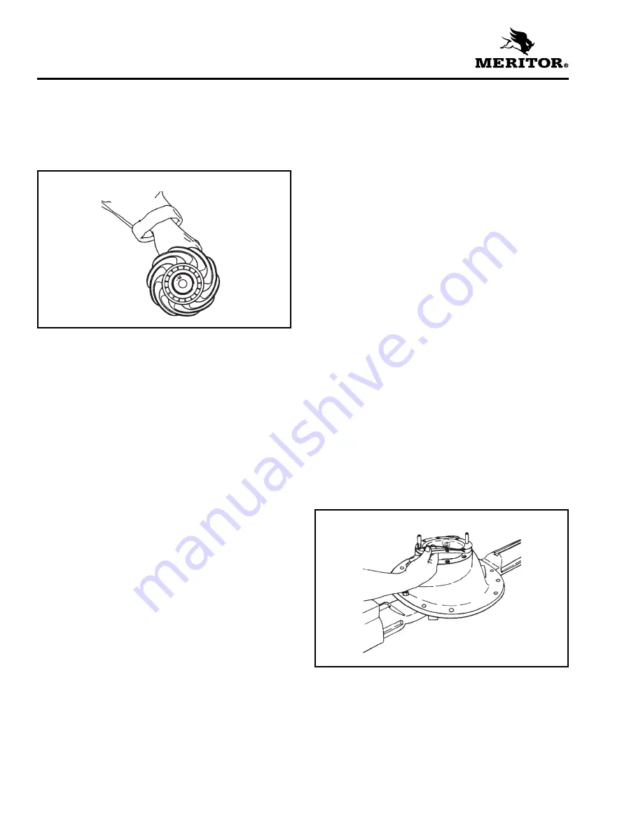
1.

Select and install the adjustment shims for 
the pinion case using guide studs (refer to 
Section 8) and apply FAG-3 sealant gasket 
on the differential case before installing the 
shims. 

Figure 5.31

.

Figure 5.30

Figure 5.31

Summary of Contents for RS-220

Page 1: ...Two Speed Differentials RS 220 RS 230 RS 240 Maintenance Manual MM 0144 Issued 04 01 2 50...

Page 2: ...arvinmeritor com To access information click on Products Services Tech Library Icon HVS Publications The screen will display an index of publications by type Additional Information Call ArvinMeritor...

Page 3: ...y Parts After Cleaning 17 Prevent Corrosion on Cleaned Parts Inspection Storage 19 Section 4 Adhesives Adhesives 20 Features of Liquid Adhesives 22 Applying Liquid Adhesives Chemical Gasket Material 2...

Page 4: ...View Exploded View 53 49 50 46 45 47 55 43 42 51 54 44 39 40 41 1 3 2 28 48 62 60 61 59 58 57 56 38 36 37 35 34 52 33 32 29 31 30 26 24 22 21 19 39 63 14 15 17 16 5 12 10 9 7 8 11 12 6 27 25 23 20 13...

Page 5: ...ng Cup Pinion Inner 13 Fasteners Case Assembly 45 Bearing Cup Outer 14 Shaft for Differential Pinions 46 Bearing Cone Outer 15 Washer 47 Pinion Bearing Spacer 16 Planetary Gears 48 Bearing Cone Pinion...

Page 6: ...e second ratio has a planetary system of straight teeth located under a hypoid ring gear First Gear Ratio High Speed At high speed the sun gear engages with the case half and blocks the operation of t...

Page 7: ...ct the driveline universal joint from the pinion input yoke or flange on the carrier 3 Place jack stands under each spring seat of the axle to hold vehicle in the raised position 4 Remove the plug fro...

Page 8: ...mer such as Chicago Pneumatic CP 4181 Puler or equivalent to loosen tapered dowels and axle shaft 2 Place the round hammer bit against the axle shaft flange between the hub studs Operate the air hamme...

Page 9: ...ifferential until it is in the low speed position LS This operation tends to eliminate the interference between the sun gear and the mouth of the housing helping to make the disassembly of the differe...

Page 10: ...9 LONG WITH ONE END SLOTTED TO FIT PLATE 4 WELD ALL AROUND AFTER PRESSING PLUG IN PIPE 5 WELD 6 SHAPE AND SIZE OF HOLES TO FIT CARRIER 7 23 1 2 CENTER TO CENTER OF PIPE 8 CHAMFER END OF PIPE FOR WELDI...

Page 11: ...and a plastic mallet Figure 2 11 2 Remove the bolts from the top of the carrier 3 Simultaneously remove the selector and the sun gear Figure 2 12 If necessary rotate the sun gear to facilitate its rem...

Page 12: ...Backlash in Section 8 Figure 2 15 8 Remove the cotter key from the right side adjustment nut Figure 2 16 9 Remove the capscrews and washers that hold the bearing caps on the carrier Figure 2 17 10 Man...

Page 13: ...the ring gear from the plain half of the case to replace some of the parts if necessary WARNING Observe all warnings and cautions provided by the tool manufacturer to avoid serious personal injury and...

Page 14: ...Separate the case halves Remove the internal components in the sequence specified in Figures 2 27 2 28 2 29 and 2 30 To disassemble the case use a press or a hammer and a brass bar making contact with...

Page 15: ...move the shafts 14 Remove the side gears carefully without loosening and mixing the bearings 15 Remove the inner and outer washers Figure 2 33 16 Place the bearings and spacers in plastic bags Remove...

Page 16: ...case Figure 2 36 4 Remove the pinion case fastening screws and washers Figure 2 37 CAUTION Do not insert wedges or chisels between the pinion and differential cases Damage to components can result 5...

Page 17: ...e inner bearing cone and bearing spacer will remain on the pinion shaft 4 If a press is not available use a leather plastic or rubber mallet to drive the pinion through the bearing cage 5 Use a press...

Page 18: ...flange area with metal or wood blocks 8 If you need to replace the pinion bearings remove the inner bearing cone from the drive pinion with a press or bearing puller The puller MUST fit under the inne...

Page 19: ...ring puller Figure 2 46 12 If equipped with a two piece spigot bearing remove the inner race from the pinion using a bearing puller 13 Remove the outer race roller assembly from the carrier using a dr...

Page 20: ...r polished parts in a hot solution tank or use strong alkaline solutions for cleaning or the smooth sealing surface may be damaged Rough Parts 1 Clean rough parts with the same method as cleaning grou...

Page 21: ...l lubricant from the bearings knuckle hub and hubcap Inspect the cup the cone and the rollers and cage of all bearings If any of the following conditions exist you must replace the bearing 1 The cente...

Page 22: ...washer seatings half rounds for installing the arms of the spiders on both halves of the satellite case 2 Side gear and pinion bearing surface 3 Diameters of the trunnion ends of the spider 4 Teeth a...

Page 23: ...the splines and for out of roundness of the flange bores Case Check for cracks on any surface or burrs on the machined parts Yoke Replace the yoke if it shows excessive wear in the retainer area Carri...

Page 24: ...alent 1 Clean the oil dirt and old adhesive from all threads and threaded holes Use a wire brush 2 Apply four or five drops of Meritor Liquid Adhesive Loctite 680 or equivalent inside each threaded ho...

Page 25: ...water for 15 minutes Have your eyes checked by a doctor as soon as possible The following silicone gasket products or equivalent can be used for Meritor components O Three Bond Liquid Gasket No TB 121...

Page 26: ...oles Carefully clean the dirt oil grease or moisture from the threaded holes and from the fastener threads This must be done with trichlorethylene or other chlorinated solvents Assemble Parts Before b...

Page 27: ...asket material Applying Silicone Gasket Materials WARNING Take care when you use silicone gasket materials to avoid serious personal injury Follow the manufacturer s instructions to prevent irritation...

Page 28: ...RNING Observe all warnings and cautions provided by the tool manufacturer to avoid serious personal injury and damage to components 5 Install a new rear bearing cone making sure that it is perfectly s...

Page 29: ...against the spigot bearing 11 Release the pressure and lower the drive pinion and spigot bearing assembly 12 Install a new snap ring with appropriate snap ring pliers Figure 5 8 13 Lubricate the bear...

Page 30: ...lues before you install the seal onto the drive pinion bearing cage Table A Models 220 224 230 Figure 5 10 Figure 5 11 PRESS Apply adhesive to this area Figure 5 12 New Bearings 1 7 4 0 N m 15 35 lb i...

Page 31: ...ng cage several times and hook a dynamometer high quality scale to the end 4 Pull the cord with the dynamometer Read the value pounds or kilograms on the scale Refer to Table E Table E Code Thickness...

Page 32: ...19 3 x 0 098 1 9 N m 16 55 x 0 113 1 9 N m Without a Press If a press is not available use the following procedure 1 Lubricate all the drive pinion bearings with the oil specified in Section 6 2 Insta...

Page 33: ...Packs Using a Caliper 1 Write down the nominal mounting dimension ND for the drive pinion This dimension is the nominal distance taken from the center of the ring gear to the rear drive pinion bearin...

Page 34: ...ing value will establish a master thickness for shim packs used for the assembly of a drive pinion whose ND dimension is equal to zero C Take note of the value obtained in Step B to use in the calcula...

Page 35: ...stall the drive pinion bearing cage with the face that will be inserted in the carrier facing down on the rear drive pinion bearing Figure 5 20 5 Install the front bearing on the other face of the dri...

Page 36: ...nch in the same cross sequence apply the following torque values 67 91 lb ft 90 125 N m Figure 5 25 11 Check if the differential case assembly bearing housing and the special tool centering disks are...

Page 37: ...shim pack Place the pointer on the centering shaft Slide the pointer across the centering shaft until maximum value is indicated Figure 5 28 Write down the maximum value Mv indicated by the pointer of...

Page 38: ...nominal dimension Csnd Number 6 engraved on the end of the drive pinion signifies that the variation in the height of the pinion in relation to the differential nominal dimension is 0 06 mm lower tha...

Page 39: ...ng Preload in this section Assemble the Main Differential and Ring Gear Assembly 1 Apply Shell 71032 Alvania EP 2 or Texaco 995 Multifak EP 2 grease in the holes of the side gears Install the bearings...

Page 40: ...the spider Figure 5 40 10 Position the tapered side gear long hub and thrust washer 11 Install the main differential case plain half without changing the original alignment 12 Install four fasteners i...

Page 41: ...and install with care as to not allow any grease to fall into the differential case Assemble the Differential Case Halves WARNING Observe all warnings and cautions provided by the tool manufacturer to...

Page 42: ...cap capscrews Tighten the fasteners according to the specifications in Section 7 2 Install the cones in the cups and mount the differential case assembly Figure 5 46 3 Install the left side adjusting...

Page 43: ...ew Assemble the Gear Shift Command Mechanism WARNING Take care when you use Loctite to avoid serious personal injury Follow the manufacturer s instructions to prevent irritation to the eyes and skin 1...

Page 44: ...ft fork Install the Differential Carrier into Axle Housing WARNING Take care when you use Loctite to avoid serious personal injury Follow the manufacturer s instructions to prevent irritation to the e...

Page 45: ...ition of the shift mechanism actuator 13 Install the washers and fastening nuts of the shift mechanism and tighten them to the torque value specified in Section 7 14 Connect the drive shaft and align...

Page 46: ...be covered with a good film of anticorrosive oil In this event the differential must be stored in a closed box until it is used to protect it from dust and other impurities Oil Change Periods New or...

Page 47: ...caps fasteners 295 360 220 265 295 360 220 265 575 705 425 520 High Torque 6 Capscrews ring gear and differential case 205 250 150 185 205 250 150 185 205 250 150 185 High Torque 7 Nuts lock plate fa...

Page 48: ...Preload 1 The preload is obtained by the correct positioning of the bearing adjusting rings Figure 8 4 Gradually tighten the X ring until the backlash of the ring gear drive pinion is eliminated Zero...

Page 49: ...measurement Figure 8 6 4 Loosen same ring X three or four notches or holes Tighten ring Y gradually to expand the bearing caps between 0 006 to 0 013 inch 0 15 0 33 mm for new bearings or 0 003 to 0...

Page 50: ...ase the backlash Loosen ring X and tighten ring Y in the same proportion to avoid altering the bearing preload Figure 8 10 Verification Process 1 Apply yellow iron oxide diluted in fine oil on some of...

Page 51: ...the drive pinion is not at the proper depth the contact can show tooth height variation If so alter the position varying the thickness of the shim pack of the drive pinion bearing case Refer to Table...

Page 52: ...ar to increase the backlash if necessary to the maximum permitted for the contact area to move towards the heel drawing closer in the manner indicated in Figure 8 14 Refer to Check Hypoid Gear Set Bac...

Page 53: ...the publication was approved for printing and is subject to change without notice or liability ArvinMeritor Commercial Vehicle Systems reserves the right to revise the information presented or discon...

Reviews: