


T. 1300 222 445 | www.melec.com.au
For further information about our Warranties please go to:
melec.com.au/legal/warranties
INSTALLATION GUIDE
11. Removed from a Zigbee Network through Coordinator or Hub Interface
From your ZigBee controller or hub interface, choose to delete or reset
the lighting device as instructed. The connected light blinks 3 times to
indicate successful reset.
Note: 1) If the device is already at factory default setting, there is no indication when factory reset again .
2) All configuration parameters will be reset after the device is reset or removed from the network.
13. Factory Reset
through
a
Zigbee
Remote (Touch Reset)
Step 2
: Set the remote or touch panel (target node) into find and bind mode, and enable it
to find and bind initiator, please refer to corresponding remote or touch panel manual
.
Step 3
: There will be an indication on the remote or touch panel that it has bound the device
successfully and can control it
.
Zigbee
Remote
14. Find and Bind Mode
Step 1
: Short press “Prog.” button 3 times (Or reset power to the device (initiator node) 3 times) to start Find and Bind
mode (connected light flashes slowly) to find and bind target node, after 180 seconds timeout, repeat the step.
Step 2:
Set the green power
remote into Learning mode,
please refer to its manual
.
Zigbee
Green Power
Remote
Step 3
: LED indicator will flash
twice to indicate successful
learning. Then the remote can
control the device.
Note: Each device can learn to
max. 20 zigbee green power remote.
16. Delete Learning to a Zigbee Green Power Remote
Step 2:
Set the paired green power remote into
Learning mode, please refer to its manual
.
Step 3
: LED indicator will
flash 4 times to indicate
successful deleting.
Step 1
: Short press “Prog.” button 3 times (Or reset power of the device 3 times) to start delete Learning mode
(connected light flashes slowly), 180 seconds timeout, repeat the step.
Step 3
: Set the remote or touch panel into Touch Reset procedure to reset the
device, please refer to corresponding remote or touch panel manual to learn how
.
Note
: Make sure the device already added to a network, the remote added to the same one or not added to any
network.
Step 1
: Reset power of the device to start TouchLink Commissioning, 180 seconds timeout, repeat this step.
Step 4
: There shall be indication
on the remote and LED indicator
on the device flashes 3 times for
successful reset.
< 10cm
Zigbee
Remote
Zigbee
Green Power
Remote
Step 2
: LED indicator flashes 3
times for successful reset.
Step 2
: Bring the remote or touch panel within 10cm of the lighting device
.
Note
: Make sure the device and the remote or touch panel are already added to the same Zigbee hub.
15. Learning to a Zigbee Green Power Remote
Step 1
: Short press “Prog.” button 4 times (Or reset power of the device 4 times) to start Learning mode
(connected light flashes twice), 180 seconds timeout, repeat the step.
12. Factory Reset Manually
Step 1
: Short press “Prog.” key for 5 times continuously or reset power to the device 5 times consecutively from the
master breaker if the “Prog.” key is not accessible.
L N
9
7
3 5
1
0
1
8
4 6
2
L N
9
7
3 5
1
0
1
8
4 6
2
L N
9
7
3 5
1
0
1
8
4 6
2
L N
DALI Add.
9
7
3
5
1
0
1
8
4
6
2
L
L1
N
N
DA/-
DA/+
Prog.
DALI
0/1-10V
Input Voltage: 110-240V AC
Output Current: 1x5A max
ZigBee to DALI+0/1-10V
2 in 1 Converter with Relay
ta:-20
℃
-+50
℃
L N
DALI Add.
9
7
3
5
1
0
1
8
4
6
2
L
L1
N
N
DA/-
DA/+
Prog.
DALI
0/1-10V
Input Voltage: 110-240V AC
Output Current: 1x5A max
ZigBee to DALI+0/1-10V
2 in 1 Converter with Relay
ta:-20
℃
-+50
℃
DA/-
L
L1
DA/+
Prog.
N
N
ML-ZIG-010D
ZigBee to DALI+0/1-10V
2 in 1 Converter with Relay
110-240V ~ 50/60Hz
Max. load: 5A Resistive
1E4
DALI
0/1-10V
DALI Add.
μ
20T 50
1.6A LED
DA/-
L
L1
DA/+
Prog.
N
N
ML-ZIG-010D
ZigBee to DALI+0/1-10V
2 in 1 Converter with Relay
110-240V ~ 50/60Hz
Max. load: 5A Resistive
1E4
DALI
0/1-10V
DALI Add.
μ
•tc=75°C
20T 50
1.6A LED
DA/-
L
L1
DA/+
Prog.
N
N
ML-ZIG-010D
ZigBee to DALI+0/1-10V
2 in 1 Converter with Relay
110-240V ~ 50/60Hz
Max. load: 5A Resistive
1E4
DALI
0/1-10V
DALI Add.
μ
20T 50
1.6A LED
8
.
WHEN DALI OUTPUT SELECTED
Zigbee Lighting Device
Step 2
: Set another device, remote or touch panel into network pairing mode and pair to the network, refer to their
manuals
.
Step 3
: Pair more devices and remotes to the network as needed, refer to their manuals.
Step 4
: Bind the added devices and remotes through Touchlink so that the devices can be controlled by the
remotes, refer to their manuals.
Note: 1) Each added device can link and be controlled by max. 30 added remotes.
2) Each added remote can link and control max. 30 added devices.
18. OTA
The device supports firmware updating through OTA, and will acquire new firmware from zigbee controller or
hub every 10 minutes automatically.
17. Setup a Zigbee Network & Add Other Devices to the Network (No Coordinator Required)
Step 1
: Short press “Prog.” button 4 times (Or reset power to the device 4 times) to enable the device to form a zigbee
network (LED indicator flashes twice) to discover and add other devices, 180 seconds timeout, repeat the step.
Zigbee
Remote
< 10cm TouchLink
0/1-10V Dimmable
Driver
ACL
ACN
DIM+
DIM-
LED+
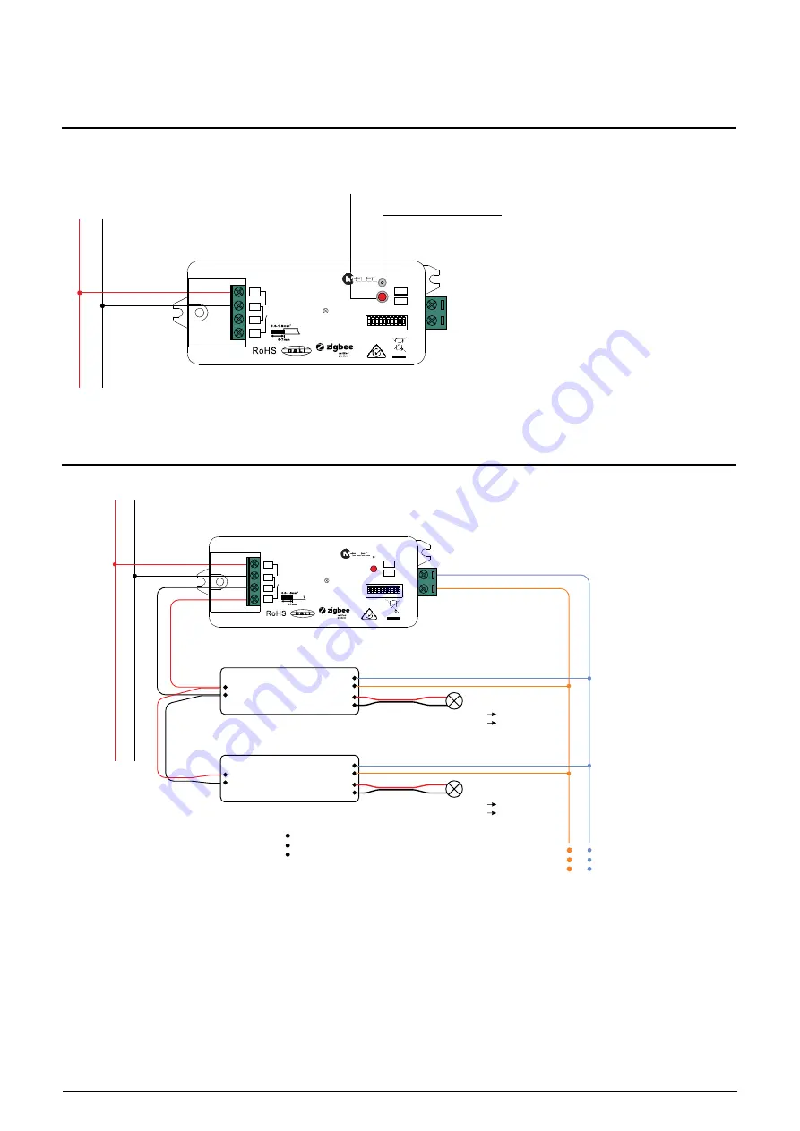
Wiring Diagram
When 0/1-10V Output Selected
L N
Max
. 5
A Rela
y
LED+ V+
LED light
9
7
3 5
1
0
1
8
4 6
2
LED-
LED- V-
When DALI Output Selected
Note
: 1) Max. 50mA DALI bus PS output to supply control current to up to 25 control devices.
2) The max. load of the relay is 5A, and the number of control gear can be switched by the relay
depending on the load of each control device.
L N
Max
. 5
A Rela
y
DALI Bus
DA
DA
DALI DT6/DT8 Control Gear
L
N
DA
DA
DALI DT6/DT8 Control Gear
L
N
LED+
LED-
LED+
LED-
LED+ V+
LED- V-
LED+ V+
LED- V-
LED light
LED light
DALI Add.
9
7
3 5
1
0
1
8
4 6
2
L N
DALI Add.
9
7
3 5
1
0
1
8
4 6
2
DA/-
L
L1
DA/+
Prog.
N
N
ML-ZIG-010D
ZigBee to DALI+0/1-10V
2 in 1 Converter with Relay
110-240V ~ 50/60Hz
Max. load: 5A Resistive
1E4
DALI
0/1-10V
DALI Add.
μ
20T 50
1.6A LED
DA/-
L
L1
DA/+
Prog.
N
N
ML-ZIG-010D
ZigBee to DALI+0/1-10V
2 in 1 Converter with Relay
110-240V ~ 50/60Hz
Max. load: 5A Resistive
1E4
DALI
0/1-10V
μ
20T 50
1.6A LED
DA/-
L
L1
DA/+
Prog.
N
N
ML-ZIG-010D
ZigBee to DALI+0/1-10V
2 in 1 Converter with Relay
110-240V ~ 50/60Hz
Max. load: 5A Resistive
1E4
DALI
0/1-10V
μ
20T 50
1.6A LED
Zigbee Lighting Device
Step 2
: Set another device, remote or touch panel into network pairing mode and pair to the network, refer to their
manuals
.
Step 3
: Pair more devices and remotes to the network as needed, refer to their manuals.
Step 4
: Bind the added devices and remotes through Touchlink so that the devices can be controlled by the
remotes, refer to their manuals.
Note: 1) Each added device can link and be controlled by max. 30 added remotes.
2) Each added remote can link and control max. 30 added devices.
18. OTA
The device supports firmware updating through OTA, and will acquire new firmware from zigbee controller or
hub every 10 minutes automatically.
17. Setup a Zigbee Network & Add Other Devices to the Network (No Coordinator Required)
Step 1
: Short press “Prog.” button 4 times (Or reset power to the device 4 times) to enable the device to form a zigbee
network (LED indicator flashes twice) to discover and add other devices, 180 seconds timeout, repeat the step.
Zigbee
Remote
< 10cm TouchLink
0/1-10V Dimmable
Driver
ACL
ACN
DIM+
DIM-
LED+
Wiring Diagram
When 0/1-10V Output Selected
L N
Max
. 5
A Rela
y
LED+ V+
LED light
9
7
3 5
1
0
1
8
4 6
2
LED-
LED- V-
When DALI Output Selected
Note
: 1) Max. 50mA DALI bus PS output to supply control current to up to 25 control devices.
2) The max. load of the relay is 5A, and the number of control gear can be switched by the relay
depending on the load of each control device.
L N
Max
. 5
A Rela
y
DALI Bus
DA
DA
DALI DT6/DT8 Control Gear
L
N
DA
DA
DALI DT6/DT8 Control Gear
L
N
LED+
LED-
LED+
LED-
LED+ V+
LED- V-
LED+ V+
LED- V-
LED light
LED light
DALI Add.
9
7
3 5
1
0
1
8
4 6
2
L N
DALI Add.
9
7
3 5
1
0
1
8
4 6
2
DA/-
L
L1
DA/+
Prog.
N
N
ML-ZIG-010D
ZigBee to DALI+0/1-10V
2 in 1 Converter with Relay
110-240V ~ 50/60Hz
Max. load: 5A Resistive
1E4
DALI
0/1-10V
DALI Add.
μ
20T 50
1.6A LED
DA/-
L
L1
DA/+
Prog.
N
N
ML-ZIG-010D
ZigBee to DALI+0/1-10V
2 in 1 Converter with Relay
110-240V ~ 50/60Hz
Max. load: 5A Resistive
1E4
DALI
0/1-10V
μ
20T 50
1.6A LED
DA/-
L
L1
DA/+
Prog.
N
N
ML-ZIG-010D
ZigBee to DALI+0/1-10V
2 in 1 Converter with Relay
110-240V ~ 50/60Hz
Max. load: 5A Resistive
1E4
DALI
0/1-10V
μ
20T 50
1.6A LED


