


English
Translation of the original operating and assembly instructions
FGHJ INOX_Manual-en_R0
ID 76429
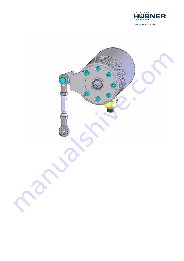
Operating and Assembly Instructions
Incremental Hollow Shaft Encoder FGHJ INOX
Read the operating and assembly instructions prior to
assembly, starting installation and handling!
Keep for future reference!
Summary of Contents for FGHJ INOX
Page 23: ...Incremental Hollow Shaft Encoder FGHJ INOX FGHJ INOX_Manual en_R0 23 12 Dimension drawings ...
Page 24: ...Incremental Hollow Shaft Encoder FGHJ INOX 24 FGHJ INOX_Manual en_R0 ...
Page 25: ...Incremental Hollow Shaft Encoder FGHJ INOX FGHJ INOX_Manual en_R0 25 ...
Page 26: ...Incremental Hollow Shaft Encoder FGHJ INOX 26 FGHJ INOX_Manual en_R0 ...
Page 27: ...Incremental Hollow Shaft Encoder FGHJ INOX FGHJ INOX_Manual en_R0 27 ...
Page 28: ...Incremental Hollow Shaft Encoder FGHJ INOX 28 FGHJ INOX_Manual en_R0 ...
Page 29: ...Incremental Hollow Shaft Encoder FGHJ INOX FGHJ INOX_Manual en_R0 29 ...
Page 30: ...Incremental Hollow Shaft Encoder FGHJ INOX 30 FGHJ INOX_Manual en_R0 ...


