


MeiG
Product
Manual
of
SLM750
Module
SLM750
Module
Hardware
Design
Page 35, total 84 pages
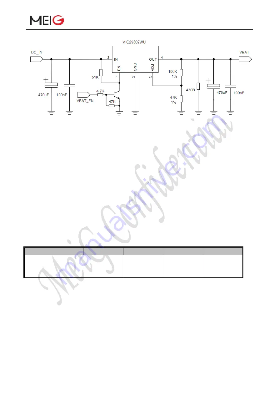
Figure 6 DC power supply circuit
3.6.4 VDD_EXT voltage output
If SLM750 module turns on normally, there is a voltage output of 1.8V, current load 80mA in
PIN7. You can use the output voltage as external power supply, for example level reference, and
judge if the module is turned on by reading pin level status.
3.7 Turn On and Off
3.7.1 Turn on module using the PWRKEY
Table 7.1: Description of PWR_KEY pin
Pin name
Pin number
Function
DC features
Description
PWR_KEY
21
Turn on/off the
module
V
IH
max=2.1V
V
IH
min=1.3V
V
IL
max=0.5V
When SLM750 is in power down mode, it can be turned on to normal mode by driving the
PWRKEY pin to a low level for at least 100ms. It is suggested that you use an open set driver
circuit to control PWRKEY pin. After STATUS pin (require external pull-up) outputting a low level,
PWRKEY pin can be released. Reference circuit is illustrated in the following figure:


