Chapter 6: Motor Wiring
47
6.5.3 Closed-loop Step Motors
DSPpro controllers can control step motors with encoder feedback. Closed-loop steppers are
controlled by a PID algorithm running on the DSP in real time. The boards accept TTL level (0v
to 5v, 40mA max) encoder input from either differential or single-ended encoders. Differential
encoders are preferred due to their excellent noise immunity. The connections for a single ended
encoder are identical to a differential encoder except nothing should be connected to channel A-
and channel B-. The A- and B- lines are pulled up internally to 2.5 volts.
Encoder signals are read in quadrature. This means every line on the encoder will produce a
rising edge and a falling edge on channels A+ and B+ which is interpreted by the DSPpro as four
encoder counts.
Connecting closed-loop step motors to the board is similar to servo motors, except that the step
and direction lines are connected instead of the analog signal. The minimum connections are:
•
Step + (or Step -)
•
Dir (or Direction -)
•
Signal Ground
•
Encoder A + and B + lines
•
+ 5 Volts
Note that when only Step+ or Step- is used, it is often necessary to jumper unused terminals on
the step driver. Consult the manual on your step drive prior to connection.
In general, use Step+ for drives with active high logic, and use Step- for drives with active low
logic. Also, note that both Step+ and Step- lines can be connected to drives with differential
inputs. If in doubt, fax the drive pin-outs to MEI along with any questions.
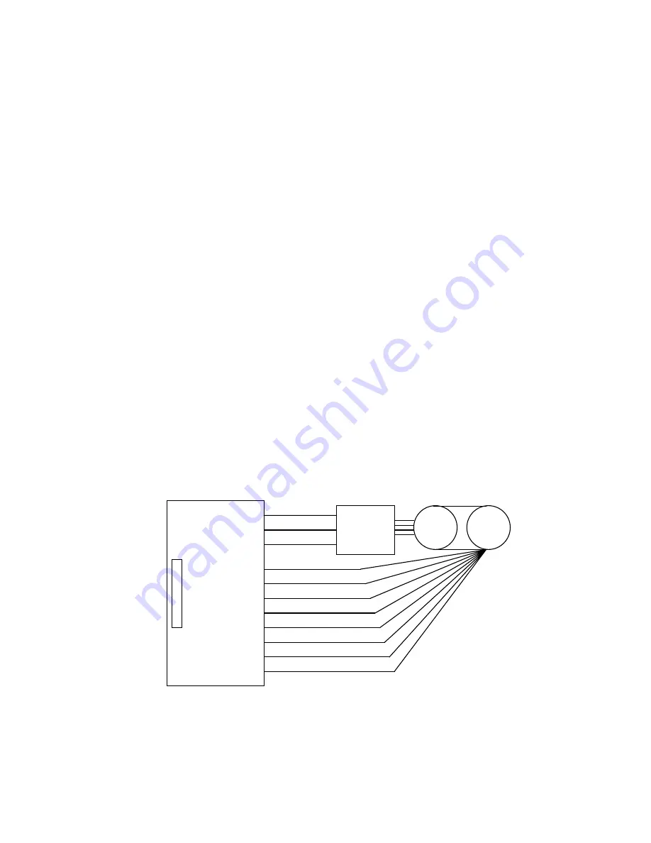
A sample wiring diagram for a step motor with differential encoder follows:
STC-26
Stepper
Drive
1
10
GND
3
4
5
6
7
8
Encoder A+
Step +
Encoder A-
Encoder B+
Encoder B-
Encoder Index+
Encoder Index-
To:
Motor
Encoder
1
2
GND
+5 volts
12
Dir
DSPpro-VME
Artisan Technology Group - Quality Instrumentation ... Guaranteed | (888) 88-SOURCE | www.artisantg.com


