


26
written in the user program to modify the MTC configuration parameters. MC main module station
number is 0, MTC station number is 1, write a simple McBus-based user program. The main module
provides some special D and M components for MTC. For M components, the user can operate directly
(see appendix I list of MCbus dedicated M components). For the D element, the user can operate
through the following five command words.
1) read command 4: read the measured value of channel 1 ~ 4, the output value of heating control and
the current execution section of multiple segments, the output state of refrigeration control, the error state
word, the wrong address of setting value range, and the cold end temperature.
2) read command 5: read the refrigeration control output value of channel 1 ~ 4.
3) write command 6: write channel type of channel 1 ~ 4, temperature setting value, control output cycle,
temperature control starts and stops.
4) write command 7: write the heating side proportional band of channel 1 ~ 4, the heating side integral
time, the heating side differential time.
5) write command 8: write the proportional band of the cooling side of 1-4 channels, the integral time of
the cooling side, and the differential time of the cooling side. The definition of the MCbus communication
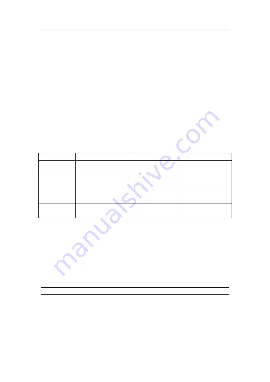
buffer (the D element in the main module) is shown in table 3-2.
Table 3-2 MCbus communication buffer (D element in the main module) definition table
D elements
Definition
D elements
Definition
D7500~D7531
MCbus communication
buffer for main module
D7628~D7659
MCbus communication
buffer for MTC#4
D7532~D7563
MCbus communication
buffer for MTC#1
D7660~D7691
MCbus communication
buffer for MTC#5
D7564~D7595
MCbus communication
buffer for MTC#2
D7692~D7723
MCbus communication
buffer for MTC#6
D7596~D7627
MCbus communication
buffer for MTC#3
D7724~D7755
MCbus communication
buffer for MTC#7
3.2.5 Programming
This section through the "man-machine intPLC+MTC" this application system to explain the
general use of MTC thermostat. Taking MEGMEET series PLC as an example, ModBus is used for
communication between man-machine interface and PLC, and McBus is used for communication
between PLC and MTC. PLC station number is 0 and MTC station number is 1. 1. Set the parameters of
MTC. See chapter 4 for the MTC wizard Settings.
2. With the D and M components open to the user, PLC and man-machine interface can be used to
monitor and measure MTC. Let's expand on that.
Note: the D elements listed in table 3-2 and the dedicated M elements in the attachment are the
dedicated soft elements of the thermostat. Users are not allowed to use them for other purposes.
MTC provide some dedicated D and M components. For dedicated M components, users can operate
directly (see appendix I list of MCbus dedicated M components). For the D element, the user can operate
through the five command words described above.
Read command 4
1. The main module defines the frame with the MCbus communication buffer. D component definitions
are shown in the following table


