


21
Input/output
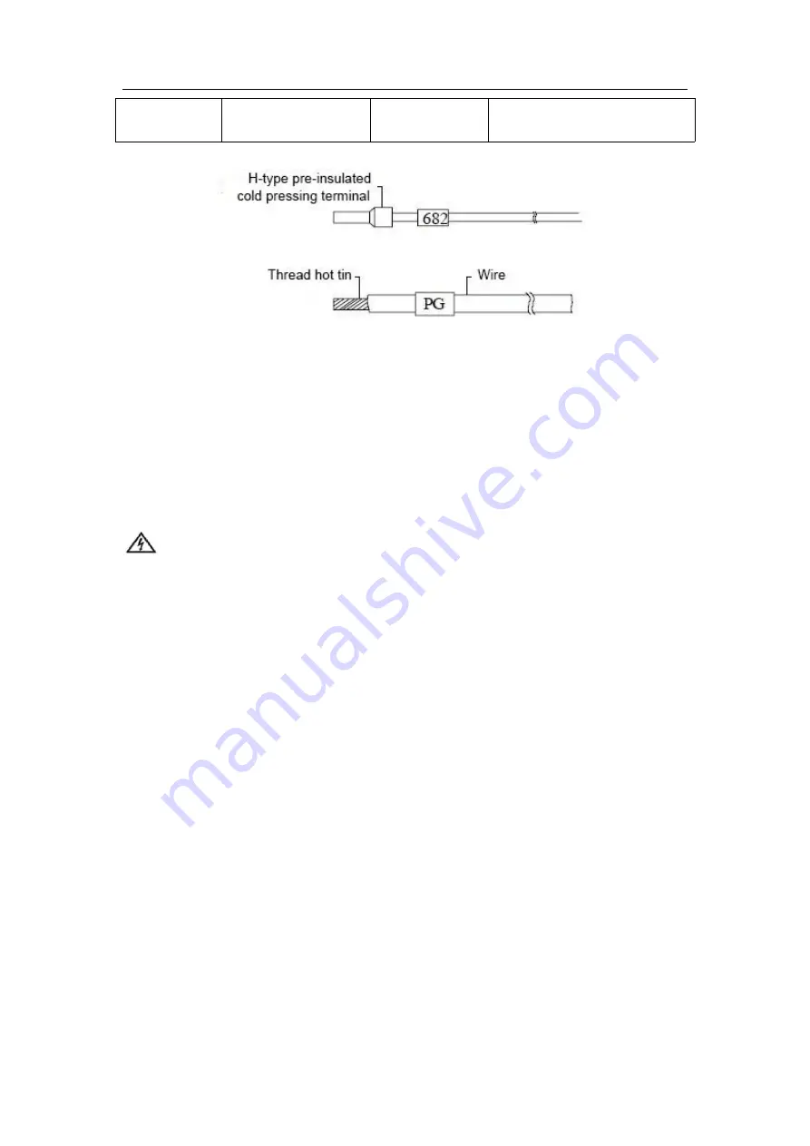
signal cable
1.0
~
2.0mm²
AWG12
,
AWG18
H1.5/14
pre-insulated
tubular
terminal, or wire soldering
The recommended cable preparation method is shown in figure 2-5.
Figure 2-5 MTC connection cable preparation method recommended
Fix the finished cable end on the MTC terminal with screws. Pay attention to the correct position of the
screws. The tightening torque of the screws is between 0.5 and 0.8Nm, ensuring reliable connection
without damaging the screws.
2.2.4 Connect power cable
The power supply can use the 24Vdc power output from the main module, or other power supply that
meets the requirements. The user shall connect the power cord to the power supply input terminal head
in case of power failure, and then insert the terminal head into the DC24V power supply input terminal of
MTC.
danger
1
.
The power supply of MTC is 24Vdc. Be sure to check and confirm before wiring and energizing
to avoid equipment damage and other losses caused by misuse.
2
.
Do not connect and disassemble the cables live to avoid electric shock and equipment
damage.
3
.
When inserting the power supply input terminal and other signal lines into MTC, the installation
must be reliable to avoid electric shock accident, equipment damage and abnormal operation
caused by terminal shedding
2.2.5 Connect input/output signal wire
When wiring the system, there are often multiple cable ends connected to the same terminal, such as
24V+, 24V-, output group common terminal COM and other wiring. It is suggested to extend the
connection by means of extension wiring, and the corresponding identification can make the connection
convenient and reliable and the wiring concise.
2.2.6 Connect communication cable
The connection methods of communication lines are different in different system networking modes.
1.The temperature controller is connected to the main PLC module of MEGMEET. The user needs to use
twisted pair to connect the RS485 communication terminal of MTC and the
RS485 communication terminal of the main module (see the user manual of the relevant main module).
As shown in Figure 2-6.


