Dynascan Manual (RT3005G) v_0611
Page 50
© Copyright Measurement Devices Limited
Copying of the materials in this document is prohibited
Issue 1
18.
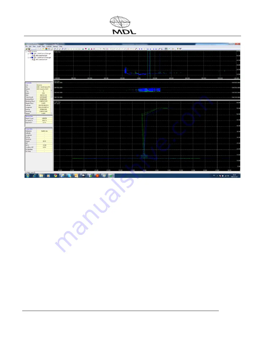
You will see that the two images are not parallel and so you must click the
View=Validate icon and then the Calibrate Alignment icon to bring up the values box.
19.
Select Pitch and manually enter values in the settings box until the images are parallel.
Use small values to start (e.g. 1) and after entering the value click on roll and then back
to pitch for the change to take effect.
20.
When you are happy with the value click transfer and then select the template plus all
files and use Relative (Add) from the dropdown menu.
21.
Repeat steps 13 and 14 before starting on the Heading calibration.
22.
When calibrating Heading choose two files on either side of the pole but in the same
direction and then select the validator icon.
23.
Follow steps 7 and 8 above and create a user defined line the same as for Pitch (at 90
to the roll line)
24.
Make the slice box fit the poles and you should see two images in the swathe view.


