McHale 991 Operator'S Instruction Manual Download Page 57

McHale


991 High Speed

 Round Bale Wrapper

57

9

Road traffic safety & operation

9.1  Before travelling on any public roadway

The following must be checked, as a minimum requirement, before moving the 
machine on a public road.

1.

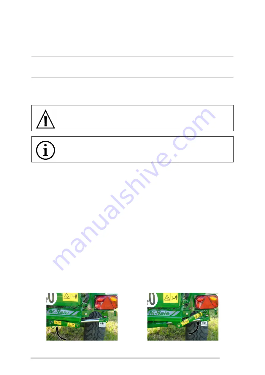
Bale lift arm must be in the fully raised position. The transport lock must be in 
the locked position while travelling on the road.

2.

The hydraulic supply must be turned off and protected from accidental 
activation by disconnecting the hydraulic feed line. Support all loose lines in a 
safe manner.

3.

Ensure the lights are connected and working correctly. The bale damper must 
be raised to comply with lighting regulations.

4.

Ensure the electronic control box is switched off.

5.

If plastic film is to be transported on the machine it must only be done so on the 
holders provided and secured, if necessary.

6.

Ensure that the knife guard is closed on the cut and hold, to prevent injury.

7.

Ensure that the tyres are set to the correct pressure as per safety decal and 
according to the specifications. 

(See ‘General specifications’)

8.

Attention must be paid to the maximum travel speed-limit of 40 km/h.

9.

Ensure that all the national road traffic regulations relating to the country are 
fulfilled i.e. the use of safety chains may be mandatory in certain countries.

WARNING: Complete a full inspection before travelling on the road

Ensure that a full inspection is completed every time before attempting 
to go on to a public roadway, always think and practice safety!

NOTE: Check lighting system before travelling on the road

Before travelling on a public road, the operator must ensure that the complete 
(tractor and machine) lighting system is in a fully functioning condition.

Transport lock, unlocked

Transport lock in the locked position

Summary of Contents for 991

Page 1: ...Ballinrobe Co Mayo F31 K138 Ireland Tel 353 94 9520300 Email sales mchale net Website www mchale net CLT00218_5 01 5 5 I S EN ISO 9001 2015 991 High Speed Round Bale Wrapper Operator Instruction Manual Issue 5 ...

Page 2: ...just select Current page if that is sufficient This is the original operator manual with Original Instructions The English language version of the operator manual is the source document for all translations If there is any conflict as to the accuracy or content of any translation the English source manual remains the authorised document No part of this manual may be reproduced distributed or trans...

Page 3: ...achine immediately and to use only genuine McHale spare parts as these are designed and manufactured to the same standard as the original machine Spare parts can be obtained from your McHale dealer Throughout this manual there are links to other relevant sections of the manual to guide the reader to additional information to convey the complete message These links are in grey italic font See the e...

Page 4: ... clear of moving parts 12 3 7 Trained operator criteria 13 3 8 In the event of a fire 13 3 9 General safety warnings 14 4 Specific safety warnings 19 4 1 Electronic safety warnings 19 4 2 Hydraulic safety warnings 19 4 3 Noise level 20 4 4 Fire precautions 20 4 5 Safety instruction decal locations 21 4 6 Safety warnings instructions explained 22 4 7 Machine lifting guidelines 27 4 8 Jacking guidel...

Page 5: ...y 57 10 Field operation wrapper adjustments 58 10 1 Drawbar height 58 10 2 Dispenser height 59 10 3 Table rollers belts 59 10 4 Adjusting table magnets 60 10 5 Bale damper lift height 63 10 6 Bale damper drop speed 63 10 7 Table drive roller shearbolt replacement 64 10 8 Gearbox cross shaft roll pin replacement 64 10 9 Cut hold accumulator pressure 65 10 10 Chain adjustments 66 11 Machine maintena...

Page 6: ...machine paying particular attention to the following Safety instructions Functions Controls hydraulic electrical It is highly recommended to get acquainted with any new machinery slowly Take time to learn and understand all of the features of the machine Proficiency will increase as more experience is obtained If you have any questions in relation to the instructions in the manual please contact y...

Page 7: ...r the purpose of storing as fodder for feeding livestock This designation includes the movement of the machine between fields by track or road incidental to the machine s main use The manufacturer will not be held responsible for any loss or damage resulting from machine applications other than those specified above Any other use the machine may be put to is entirely at the owner operator s risk T...

Page 8: ...2 Front view No Machine function 1 Side tip damper 2 Lift arm 3 Bale support bobbin 4 Rotating table 5 Cut and hold 6 Bale detect sensor 7 2 x quick fit dispensers 8 Spare film roll holders 9 Shearbolt unit 10 Road lights 1 2 3 4 5 3 9 7 7 8 10 6 ...

Page 9: ...eight to top of rollers 1 25 m 4 1 Transport weight unladen 2 125 kg 4 685 lbs Axle weight unladen 1 900 kg 4 189 lbs Maximum road speed 40 km h 25 mph Attachment Pin hitch Towing tractor requirements 35 kW 47 hp Electrics 12 V DC 7 A approx Hydraulic systems Open centre closed centre load sensing Minimum hydraulic pressure 170 bar 2 465 psi Minimum hydraulic flow rate 22 l min 4 8 gal min Maximum...

Page 10: ...strong stubble which may have a tendency to puncture the film as it allows the bale to land on its edge which has a much higher degree of film coverage It is also very useful on hilly sloping ground as it can prevent bales from rolling when they land on their side Details Type Field pressure Road pressure Part No 340 55 16 133 A8 Vredestein Flo 3 4 bar 3 2 bar CWH00022 Side tip Side tip damper Dis...

Page 11: ...cates a potentially hazardous situation that if not avoided could result in machinery damage or personal injury NOTE This symbol is used to identify special instructions or procedures which if not followed strictly could result in machinery damage ENVIRONMENT This symbol reminds you to respect the environment in relation to the correct disposal of waste material 3 2 Follow all safety instructions ...

Page 12: ... strictly forbidden while operating machinery and driving as these impair the operator s attention 3 5 In case of emergencies In the event of any accident emergency equipment should be kept close at hand A first aid kit and fire extinguisher along with emergency phone numbers should always be available to machine operators 3 6 Stay clear of moving parts Serious injury or death can result from enta...

Page 13: ... this machine and have a valid tractor driver s licence The operator must be in full control of his her senses and must not be under the influence of any alcohol or drugs prescribed or otherwise The operator must have read and understood all aspects of the operator manual in order to operate maintain and clean the machine Ideally they should also receive training from their McHale Dealer It is onl...

Page 14: ...ully understood this manual are qualified to operate this machine The owner of this machine is obliged by law to ensure that every operator understands all of the functions controls working processes and safety warnings before operating the machine See Trained operator criteria Safety devices All safety devices such as guards protection parts and safety controls must be in place and in fully funct...

Page 15: ... ensure that all covers are closed and all safety devices are in operating mode The operator must ensure that there is no person in the Danger Zone Always be familiar with the health and safety requirements that may be in force in the country of use During operation While operating this machine on hilly or sloping ground the operator must take extra precautions in particular the Danger Zone is inc...

Page 16: ... and repair work exceeding the content of this manual should only be carried out by qualified persons or your McHale dealer When conducting maintenance work tie long hair behind your head Do not wear a necktie necklace scarf or loose clothing when you work near the machine or moving parts Rotating machinery parts can entangle loose clothing long hair or dangling jewellery faster than a victim can ...

Page 17: ...ed lines can be accidentally damaged when heat goes beyond the immediate flame area Regular clean down is recommended in order to maintain the machine in a safe and reliable working condition McHale recommend that the machine be blown down with an air line as opposed to a pressure washer due to the dangers involved with pressure washing and to protect the overall paint work on the machine If despi...

Page 18: ...rear window of a tractor Children under 16 years of age should never operate power driven machinery Keys should be removed from vehicles and controls left in neutral Lower any implements or loaders to the ground and apply the hand brake Do not allow children to use bales of any description for playing It is very easy to fall from stacked bales resulting in serious injury or fall between them leadi...

Page 19: ... pressure can penetrate the skin and cause injury Beware of pipes under accumulator pressure depressurise lines by unthreading connections extremely slowly Hydraulically actuated devices must be blocked mechanically against movement before working on the machine If any hoses are removed or replaced ensure they are marked and re installed to the correct position during re assembly Check hoses month...

Page 20: ...ed to operate this machine with closed cabin windows 4 4 Fire precautions Be aware that crops are easily inflammable Do not smoke or make use of any open fire next to the machine A functioning fire extinguisher should always be available on the tractor The machine is to be kept clear of oil grease crops string plastic or any other flammable material at all times Do not continue to work with overhe...

Page 21: ...McHale 991 High Speed Round Bale Wrapper 21 4 5 Safety instruction decal locations ...

Page 22: ...cals are damaged or missing they are available from your McHale dealer The relevant part numbers are shown in brackets The decals featured on the machine are displayed with their meanings below Free flow return to tank CST00006 Danger of rotating parts foreign objects Keep clear of machine while working CST00014 Turn off and remove key from tractor Read and understand the manual before working on ...

Page 23: ...rapper 23 Keep hands out of crush area CST00019 Keep hands out of the trap area CST00026 Keep clear of rotating table CST00028 Max table speed 30 rpm CST00031 Lifting hook location CST00032 Keep clear of bale damper crush area CST00048 ...

Page 24: ...lastic film path through dispenser CST00049 Bale damper skid adjustment CST00050 Read instruction manual CST00057 Support table before working under it Refer to the instruction manual CST00059 Grease daily CST00060 Bale damper drop speed adjustment CST00061 ...

Page 25: ...ng used on the road See Road traffic safety operation CST00063 Grease pin immediately after fitting the lift arm CST00105 Do not dismantle High pressure always CST000115 Diagram of plastic film path through rear dispenser CST00191 Dispenser height setting for front dispenser CST0192 ...

Page 26: ...eight setting when wrapping with two rolls of film CST00193 Check tyre pressure CST00257 Tie down points CST00901 Jacking points CST00923 Keep clear of the bale lift arm and auto load paddle as unexpected movement can occur CST00961 991 series chassis plate ...

Page 27: ...s 750 kg per chain or strap when using the four lift eye locations on the chassis shown below The crane or lifting device must be capable of lifting a minimum load of 2 5 tonnes 2 500 kg Never go under a suspended machine or attempt to try and stop it if it is moving erratically death or serious injury may result Always be observant of people and objects around the suspended machine and do not all...

Page 28: ... Suitable well maintained equipment shall be used to raise the machine Never go under the machine while it is raised off the ground Introduce the jack from the rear of the machine until it is directly under the jacking area Slowly raise the jack ensuring that there is solid contact between the jack and the machine before raising off the ground WARNING Do not rely solely on a hydraulic jack Ensure ...

Page 29: ...for a vertical load of at least 1 100 kg and a D value of at least 50 kN 2 female quick release for hydraulic power supply of minimum 20 l min 180 bar 3 female quick release for return line must be free flow to tank 4 12 V 7 pin socket for lighting 5 12 V 20 A socket or battery power cable machine loom to control box shown NOTE Use good quality oil Ensure that the tractor has clean good quality hy...

Page 30: ...rt no CVA06004 This plug is used for both open centre and load sensing hydraulic systems The hydraulic valve is set up to this specification when leaving the factory When using load sensing hydraulics always set the tractor oil flow to achieve 30 rpm on the table using the flow control on the tractors auxiliary valve 2 Plug B part no CVA06001 This setting is used for closed centre hydraulic system...

Page 31: ...freeflow to the tank It is very important to ensure that it is in freeflow to get the best results from the wrapper 6 Plug the 7 pin lighting plug into the 7 pin socket on the tractor 7 Secure the control unit in the tractor cab using the V brackets and fasteners provided If there is no cab on the tractor secure as appropriate bearing in mind the box is not waterproof 8 Screw the 37 pin socket on ...

Page 32: ...half attaches to the tractor cab allowing for quick placement removal every time it is used Ensure that the cable to the machine is not under tension and not near sharp edges etc The electric power supply is obtained from the socket of the tractor Connect the supplied fused electric power lead to the tractor battery ensuring to route away from sharp edges and hot surfaces The control box is not wa...

Page 33: ... ensure a good airtight package The operator needs to ensure that the bale is correctly wrapped It is good practice to periodically check the bales after being wrapped for any torn split or punctured plastic film If the stubble in a particular field has a tendency to puncture the plastic film it is strongly advised to wrap the bales at the stack where there may be more control over ground conditio...

Page 34: ...d prolonged exposure to the sun Do not remove the protective cover until ready for use Film damage can cause undesired film performance and affect bale weatherability ENVIRONMENT Recycling of film roll Respect the environment Never throw away or burn the waste film or the core tube Always take waste materials to a recycling centre ...

Page 35: ...McHale 991 High Speed Round Bale Wrapper 35 This page is intentionally left blank ...

Page 36: ...control box The electronic control box is the main interface between the operator and the machine When the machine is in fully automatic mode settings must be selected before wrapping commences It is also possible to work the machine manually through the buttons on the control box Remote control receiver 1 2 3 4 5 6 ...

Page 37: ... the cycle 9 Cut hold close 10 Cut hold open 11 Table reverse slow 12 Table forward slow fast Press the button for slow speed release quickly press it again for fast Resume Restarts the wrapping or any other interruption One press of this button during wrapping will engage the slow speed Pressing again will resume full rotation speed 13 Automatic Manual mode 14 Automatic cycle start If Auto Load i...

Page 38: ... Combi trailed oo Not used on 991 B series 991 L series Combi standard IL Not used on 991 B series 991 L series Remote r97L 991 LBER with bale lift arm Cut hold at the left side of the machine Remote r94 991 LBER standard Cut hold at the front of the machine 991 BE Remote rt 991 BER remote control operation Cut hold at the front of the machine Remote r Program not in use Side Load Remote 991 LBER ...

Page 39: ...mote r t Sequence Remote R94 Sequence Remote R97L Sequence Combi Standard 1L Sequence Combi Trailed oo Sequence Side Load Remote On Film Sensor On Off IR Wired Remote Type IR Wired RF RF Learn Off Continuous On Off Auto Load To Select On Auto Load On Semi Off On Auto Load On Auto Load Lower Position To Select On Auto Load Float Position To Select Use load arm buttons to move load arm to desired po...

Page 40: ...roll of film or 2 rolls of film mode is selected c Screen 3 displays the voltage and the table speed in rpm d Screen 4 indicates whether there is a bale on the wrapper BALE 1 and a second bale being carried on the load arm BALE 2 Screen 4 is only available if Auto Load is set to On or Semi Screen 4 indicates with an arrow whether there is a bale on the wrapper BALE 1 and a second bale being carrie...

Page 41: ...rt Series Electronic Control Box contains the following counters Ten different bale counters A J which can be reset These bale counters can be used to measure the amount of bales wrapped for various customers by using a different counter for each customer Day Counter which can be reset Every bale wrapped by the machine is added to the day total count regardless of the customer counter that is curr...

Page 42: ...working screen 2 The day total counter will be displayed 3 Press the Down Arrow Button 4 or ESC Button 2 twice to return to the working display Reset the day total bale counter 1 Press the Up Arrow Button 1 twice from the working screen 2 The day total counter will be displayed 3 Press Enter Button 3 to reset it 4 Press the Down Arrow Button 4 or ESC Button 2 twice to return to the working display...

Page 43: ...Button 4 three times from the working screen 2 Press Enter Button 3 to move to the Operator Setup options Slow Down Time Wrapping Sequence Program Film Sensor Display Contrast Continuous Cycle Auto Load Setup Remote Type 3 Use the Up and Down Arrows Buttons 1 4 to select an item press Enter Button 3 to adjust the current selection setting Slow down time This setting determines when the table goes ...

Page 44: ...e normally turned On but can be switched Off from the Operator Setup Menu if film sensing is not desired or if there is a problem with a sensor To set the sensor On Off 1 Press the Down Arrow Button 4 three times 2 Press Enter Button 3 once 3 Press the Down Arrow twice to move to the Select Film Sensor Screen and press Enter 4 Use the Up and Down Arrows Buttons 1 4 to adjust the setting i e On Off...

Page 45: ...ing Remote type This option is used to select the remote control type There are 3 different types used Wired remote Infrared IR Older machines Radio frequency type RF Newer machines To select the remote type 1 Press the Down Arrow Button 4 three times to select the Operator Setup Menu 2 Press Enter Button 3 3 Press the Down Arrow Button 4 four times and press Enter 4 Select either IR WIRED RF or R...

Page 46: ... electronic control box to show that the radio frequency code has been stored ESC Button 2 can then be pressed to return to the working screen and the remote is ready to use This procedure only needs to be followed when the remote handpiece is used with an electronic control box for the first time The RF type will be automatically used once the remote frequency code has been established Up to 7 ha...

Page 47: ...when not near the machine There is a very long range with radio remotes approx 200 metres in the line of sight so care must be taken not to accidentally press any buttons even when not near the machine The control box must be in AUTO mode before any remote functions will work NOTE This equipment has been tested and found to comply with the limits for a Class A digital device pursuant to part 15 of...

Page 48: ...uences If set to On then automatic loading is controlled using the paddle sensor on the load arm The AUTO START button can also be used if necessary The load arm has three positions Lower Float and Carry After loading a bale the load arm will sit at the float position If the Float Position is set to higher than the lower position then upon approaching the bale AUTO START Button 14 is pressed the l...

Page 49: ...ion Lower Float Carry When it is correct press Enter Button 3 to store the setting for the current position and press ESC Button 2 to return to the Auto Load Menu 8 When the three settings are correct select Auto Load in the menu and set to On or Semi as required 9 Press ESC to return to the working screen More accurate settings can be achieved if the adjustments are done as the arm is moved from ...

Page 50: ...Lower the bale damper 6 Switch on the electronic control box and set to Automatic mode 7 Ensure the table is in the correct starting position See Electronic control box functions The control box needs to be set on manual to work this function 8 The machine is now ready to wrap WARNING Keep out of the Danger Zone Keep all persons outside of the Danger Zone during all machine operations See Danger Z...

Page 51: ...latches open Lower dispenser only 3 When removing an old roll push upwards to latch the top roll holder in the up position Then remove the old roll core and dispose of it responsibly 4 Sit the new roll onto the bottom roll holder and align it with the top roll holder While still holding the roll pull the cable to release the top roll holder The roll of plastic film is now held in position ...

Page 52: ...e plastic film Slide the knotted end of the film in the slot provided as shown Never attempt to clamp plastic film in the cut hold mechanism 7 Close the dispenser by releasing the latch The roll should now rest against one of the aluminium rollers Upper dispenser only 8 Pull back the handle with force and push up on the dispenser latch and then release the handle Lower dispenser only Upper dispens...

Page 53: ...er work is complete as the knife is really sharp Use protective gloves and beware of sharp knife edges WARNING Do not clamp film in the cut hold mechanism Do not attempt to clamp plastic film in the cut hold mechanism as this action may result in serious injury CAUTION Use protective gloves Use protective gloves for any manual work in this area Beware of sharp knife edges Knife guard open Knife gu...

Page 54: ...0 Gear option 64 Gear option 55 Gear option Hot climates Item Part Code Description A ADP00018 Kit dispenser gears 70 B CMH00055 Gear spur 1 5 m 60 t dispenser C CMH00175 Gear spur 1 5 m 35 t dispenser Item Part Code Description A ADP00020 Kit dispenser gears 64 B CMH00056 Gear spur 1 5 m 59 t dispenser C CMH00096 Gear spur 1 5 m 36 t dispenser Item Part Code Description A ADP00019 Kit dispenser g...

Page 55: ... now ready to side tip bales When side tipping bales the machine must be stopped during tipping 7 Reverse this procedure to change back to normal tipping The side tip rear extension piece must be removed for normal tipping if fitted 8 5 Wrapping behind the tractor The following is the recommended method for working the 991 High Speed after a tractor It assumes the bales are well shaped for wrappin...

Page 56: ... The table stops rotating when the required number of rotations is reached It is now lined up for tipping off g The table is tipped automatically if the Continuous cycle is switched on Otherwise the tip button must be pressed h The bale damper raises up and the table tips i The cut and hold closes holding and cutting the plastic film j The table and bale damper lower down the bale is lowered to th...

Page 57: ...so on the holders provided and secured if necessary 6 Ensure that the knife guard is closed on the cut and hold to prevent injury 7 Ensure that the tyres are set to the correct pressure as per safety decal and according to the specifications See General specifications 8 Attention must be paid to the maximum travel speed limit of 40 km h 9 Ensure that all the national road traffic regulations relat...

Page 58: ...chine maintenance or initial set up All of these adjustments should be checked thoroughly before the machine goes to work for the first time 10 1 Drawbar height The height of the drawbar may be adjusted to allow for the use of different tractors The wrapper should be parallel to the ground when working To change the height go through the following procedure 1 Ensure the machine is securely chocked...

Page 59: ...et in its highest position and the one roll of film must be placed in the lower dispenser See Loading plastic film 10 3 Table rollers belts The wrapper normally leaves the factory with rollers set to the correct width for a 1 250 mm diameter bale Sometimes it may be necessary to narrow the rollers for a smaller diameter bale or widen them for a larger diameter bale The belts should support the ful...

Page 60: ... the outside of the table The magnets that require adjusting are positioned furthest away from the cut hold 3 Loosen the M6 bolt and nyloc nut holding the magnets in position 4 If the table does not turn far enough push the magnets in the direction shown 5 If the table turns too far push the magnets in the direction shown 6 Tighten the M6 bolt and nyloc nut Do not overtighten as the magnets may cr...

Page 61: ...ing on where the machine stops See Troubleshooting The magnet may be adjusted as follows 1 Tip up the table and fit the safety bar 2 Identify the magnet to be changed There are two set of magnets near the outside of the table The magnets that require adjusting are positioned nearest the cut hold 3 Loosen the M6 bolt and nyloc nut holding the magnets in position and move as follows 4 If the table d...

Page 62: ...e magnet 3 Move the magnet upwards to sense when the table is nearer the chassis i e the table lowers more before indexing 4 Move the magnet downwards to sense when the table is further away from the chassis i e the table lowers less before indexing Do not push down too far as the table may hit the bale damper while indexing 5 Tighten the M6 nut 6 Remove the table safety bar and lower the table ba...

Page 63: ... the cylinder rod 3 Turn the cylinder rod to lengthen or shorten the rod eye as desired 4 Tighten the locking nut 5 Remove the support and lower the bale damper Test the machine and re adjust if necessary 10 6 Bale damper drop speed The drop speed of the bale damper may be adjusted to allow for the great variation in bale weights The bale should not be allowed to drop too quickly so as not to caus...

Page 64: ...s shaft roll pin replacement As a secondary overload protection device the gearbox cross shaft is protected by roll pins which will shear when overloaded This mainly applies to older machines as newer machines have an additional keyway which prevents this from happening If this occurs they may be replaced as follows 1 Remove the 6 x setscrews holding on the cover of the gearbox Remove the cover an...

Page 65: ...banjo bolt but do not turn the bolt 2 Wrap the spanner and bolt with a cloth to stop the oil spray then turn the bolt a half turn This should allow the oil to leak out and reduce the pressure If no oil leaks then turn the spanner a quarter turn at a time until it leaks off the oil pressure 3 Tighten the banjo bolt once the oil pressure is reduced 4 Once the cut and hold is operated again the accum...

Page 66: ... tractor power unit and ensure that it cannot be restarted while working on the machine 3 Loosen the 4 x M16 bolts holding on the motor plate 4 Turn the M16 nyloc nut to adjust the chain There should be 10 13 mm of sag in the chain 5 Tighten the 4 x M16 bolts holding on the motor plate 6 Remove the table safety lock and lower the table down WARNING When performing maintenance ensure the safety bar...

Page 67: ...ollowing procedure 1 Remove the chain guard by undoing the two handwheels 2 Loosen the 4 x M16 nuts and bolts holding on the bearings 3 Adjust the roller using the 2 x M10 adjuster setscrews on each end of the roller Always ensure both ends have been moved by the same amount 4 Tighten the 4 x M16 nuts and bolts on the bearings 5 Replace the chain guard with the two handwheels 1 2 4 1 1 3 3 ...

Page 68: ...e where a malfunction exists Contact your McHale dealer to achieve a solution Always think Safety First 11 1 Maintenance intervals The following intervals should be adhered to in order to ensure a long and efficient life for the machine and maximum safety of personnel They assume constant working during the wrapping season First 5 working hours 1 Check all nuts and bolts for tightness and tighten ...

Page 69: ... pipes 11 Check road traffic equipment lighting and transport lock bar WARNING Pay particular attention to the outer ram pin on the bale lift arm The outer ram pin connecting the ram piston to the bale lift arm is under extremely heavy load and must be greased daily If the pin is becoming difficult to grease or if there is any noticeable wear max 2 mm play then the pin must be replaced immediately...

Page 70: ...apper 70 Every week 1 Grease table roller bearings 2 Grease cross shaft bearing 3 Grease dispenser top coil roller shafts 4 Grease cut and hold plunger 5 Grease bale damper side tip latch Every month 1 Grease parking jack 2 1 4 3 5 3 1 1 ...

Page 71: ...chine If despite our advice a pressure washer is used then take extreme caution and operate from ground level only Do not point pressurized water at or near electrical components pivots points valves or bearings Never climb onto any part of the machine while pressure washing due to the fact that all metal surfaces become extremely wet and slippery and always ensure that the tractor has been shut d...

Page 72: ...inspector throughout If communication is lost with the inspector or they move within 1 1 m of moving parts or parts that have the potential to move all tractor power shall be turned off immediately ENVIRONMENT Health and safety rules for the environment It is vitally important to observe health and safety rules in order to avoid unnecessary environmental damage or danger to anybody near the machin...

Page 73: ...5 DIN 933 M6 10 14 16 M8 23 33 40 Socket head M10 45 63 75 Cap screws M12 78 110 130 DIN 912 M14 122 175 210 M16 195 270 325 Hex nuts M18 260 370 440 DIN 934 M20 370 525 630 M22 510 720 870 M24 640 900 1 080 M27 980 1 400 1 650 M30 1 260 1 800 2 160 Dimensions Metric fine thread Hex bolts M8 x 1 25 35 42 DIN 960 M10 x 1 25 48 67 80 DIN 961 M12 x 1 25 88 125 150 M12 x 1 5 82 113 140 Hex nuts M14 x ...

Page 74: ...key removed Remove the control box from the tractor and store in a dry safe environment Lubricate all pivot points and apply a thin layer of grease to all adjustment bolt threads and exposed ram rods Any components from which paint has become worn should be touched up or coated with grease to prevent rusting Remove all dirt from all chains and blow dry using compressed air 12 2 Start of season Ful...

Page 75: ...ift arm and table Symptom Reason Solution Lift arm not operating Faulty power supply electrical connections Check and correct Table rotates but bale not indexing Table drive roller shearbolt broken Replace shearbolt Table stopping in the wrong position Magnet settings Reset magnets Not starting in the correct position Start with cut hold at the rear of the machine Slow down setting in the control ...

Page 76: ...k on dispenser Replace spring Plastic getting caught around the cut hold Table down magnet set too high Reset table down magnet Symptom Reason Solution Damper slow or fails to come down Restrictor tap set too tight Adjust restrictor Damper rising during wrapping cycle High hydraulic back pressure Fit free flow return Faulty quick release coupling Replace quick release coupling Symptom Reason Solut...

Page 77: ...damaged Locate and replace Magnet broken Locate and replace Sensor magnet clearance Adjust sensor approx 10 15 mm from magnet Faulty control box Replace control box LOW BATT appears on the control box Supply voltage too low Check battery and charging system Only half the number of actual rotations is displayed on the control box One set of magnets missing Replace the missing set of magnets Control...

Page 78: ...he batteries Not pressing the Start button for long enough Press the button for 2 to 3 seconds Sunlight shining direct into the receiver infrared type receivers only Turn away or shade Operating through tinted glass infrared type receivers only Operate where glass cannot come in the way Symptom Reason Solution Dump valve on control valve leaking electronic machines Back pressure too high Ensure fr...

Page 79: ...ed to the customer with the machine Machine is reassembled correctly Tyre pressure is correct Hydraulics electrics and lighting are working New owner has been instructed on how to operate maintain the machine The PDI is included in this operator manual See Pre Delivery Inspection Form 14 3 Change of ownership pre checks The PDI pre delivery inspection form that is filled out on the commissioning o...

Page 80: ...ame of manufacturer Address McHale Engineering Ballinrobe Co Mayo Ireland F31 K138 Is also in conformity with the provisions of the following other EU directives 2014 30 EU Electromagnetic compatibility EMC Technical file compiled by James Heaney c o McHale Engineering Ballinrobe Co Mayo Ireland F31 K138 Harmonised standards applied EN ISO 12100 Safety of machinery General principles for design Ri...

Page 81: ...UHFWO EHIRUH FRXSOLQJ PDFKLQH WR WUDFWRU 7RUTXH DOO EROWV KHFN GLVSHQVHU V DUH UXQQLQJ VPRRWKO IUHH IURP GDPDJH RU JULW KHQ KLWFKHG WR WUDFWRU FKHFN WKDW WKH PDFKLQH LV SDUDOOHO ZLWK WKH JURXQG GMXVW GUDZEDU LI QHFHVVDU WWDFK SLQ SOXJ IRU OLJKWLQJ V VWHP 7KH RSHUDWRU PXVW EH IXOO DZDUH RI DOO KD DUGV FRQWUROV HOHFWULF K GUDXOLF DOO IXQFWLRQV VDIHW GHYLFHV RI ERWK WKH PDFKLQH DQG WKH WUDFWRU RQQHFW...

Page 82: ...cturer concerned This Limited Warranty does not apply to failure through normal wear and tear to damage resulting from negligence or from lack of inspection from misuse from lack of maintenance and or if the machine has been involved in an accident lent out or used for purposes other than those for which it was intended by the company This Limited Warranty will not apply to any product that has be...

Page 83: ...s must be free from dirt and oil If a part is returned in an unfit state the claim will be refused If damaged parts have been returned to the company and warranty is refused the dealer is allowed a period of one month from the date of receiving our notification to request the return of the damaged parts to the dealer site Further conditions limits of application and responsibility This Limited War...

Reviews: