McConnel 1.5M Operator'S Manual Download Page 19


VEHICLE / TRACTOR PREPARATION 


We recommend vehicles are fitted with cabs 
using ‘safety glass’ windows and protective 
guarding when used with our machines.  
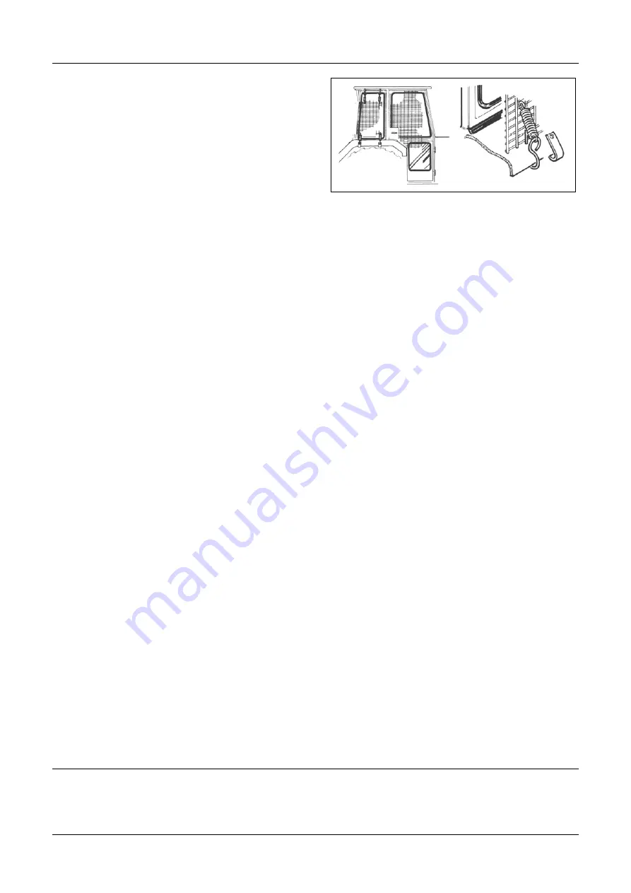
Fit Operator Guard (Part No. 7313324) using 
the hooks provided. Shape the mesh to cover 
all vulnerable areas. The driver must be 
looking through mesh and/or polycarbonate 
glazing when viewing the flail head in any 
working position - unless the vehicle/ cab 
manufacturer can demonstrate that the penetration resistance is equivalent to, or higher 
than, that provided by mesh/polycarbonate glazing. If the tractor has a roll bar only, a frame 
must be made to carry both mesh and polycarbonate glazing. The operator should also use 
personal protective equipment to reduce the risk of serious injury such as; eye protection 
(mesh visor to EN1731 or safety glasses to EN166), hearing protection to EN352, safety 
helmet to EN297, gloves, filter mask and high visibility clothing. 


Vehicle Ballast:

 It is imperative when attaching ‘third-party’ equipment to a vehicle that the 

maximum possible stability of the machine and vehicle combination is achieved – this can be 
accomplished by the utilisation of ‘ballast’ in order to counter-balance the additional 
equipment added.  


Front weights

 may be required for rear mounted machines to place 15% of total outfit 

weight on the front axle for stable transport on the road and to reduce ‘crabbing’ due to the 
drag of the cutting unit when working on the ground. 


Rear weights

 may be required to maintain a reasonable amount of rear axle load on the 

opposite wheel from the arms when in work; for normal off-ground work i.e. hedge cutting 
this should be 20% of rear axle weight or more for adequate control, and for ground work i.e. 
verge mowing with experienced operators, this can be reduced to 10%. 
All factors must be addressed in order to match the type and nature of the equipment added 
to the circumstances under which it will be used – in the instance of Power Arm hedgecutters 
it must be remembered that the machines centre of gravity during work will be constantly 
moving and will differ from that during transport mode, therefore balance becomes critical. 


Factors that affect stability: 


Centre of gravity of the tractor/machine combination. 


Geometric conditions, e.g. position of the cutting head and ballast. 


Weight, track width and wheelbase of the tractor. 


Acceleration, braking, turning and the relative position of the cutting head during these operations. 


Ground conditions, e.g. slope, grip, load capability of the soil/surface. 


Rigidity of implement mounting. 


Suggestions to increase stability: 


Increasing rear wheel track; a vehicle with a wider wheel track is more stable. 


Ballasting the wheel; it is preferable to use external weights but liquid can be added to around 75% 

of the tyre volume – water with anti-freeze or the heavier Calcium Chloride alternative can be used. 


Addition of weights – care should be taken in selecting the location of the weights to ensure they are 

added to a position that offers the greatest advantage. 


Front axle locking (check with tractor manufacturer). 


NOTE: The advice above is offered as a guide for stability only and is not a guide to vehicle strength. It is 

recommended that you consult your vehicle manufacturer or local dealer to obtain specific advice on 
this subject, additionally advice should be sought from a tyre specialist with regard to tyre pressures and 

ratings suitable for the type and nature of the machine you intend to fit. 


Summary of Contents for 1.5M

Page 1: ...Publication 939 May 2019 Part No 24214 39 McCONNEL MULTISAW 1 5M 2 0M 2 5M Models Operator Manual...

Page 2: ...ding in period of a new machine it is the customer s responsibility to regularly inspect all nuts bolts and hose connections for tightness and re tighten if required New hydraulic connections occasion...

Page 3: ......

Page 4: ...mple may require particular care when packing to avoid damage in transit 1 04 This warranty does not extend to any product from which McConnel Ltd s serial number plate has been removed or altered 1 0...

Page 5: ...d be undertaken within two days of the failure Claims submitted for repairs undertaken more than 2 weeks after a failure has occurred or 2 days after the parts were supplied will be rejected unless th...

Page 6: ...e deemed to be a waiver of any other term 4 02 If any provision of this limited warranty shall violate any applicable law and is held to be unenforceable then the invalidity of such provision shall no...

Page 7: ......

Page 8: ...cally updated to ensure you have access to the latest version of this manual please visit the manuals library on our website where an up to date version can be referenced online or downloaded https ww...

Page 9: ......

Page 10: ...ne 9 Machine Attachment 10 Hydraulic Installation 12 Belts Access 12 Operation 13 Maintenance 14 Initial Maintenance 14 Routine Maintenance 14 Checking Belt Tension 14 Tensioning Belts 15 Belt Tension...

Page 11: ......

Page 12: ...rms are applicable to the machine when fitted to the tractor and viewed from the rear these terms also apply to tractor references SERIAL PLATE All machines are equipped with a serial number plate con...

Page 13: ...machine SPECIFICATIONS Specification Model Multisaw 1500 HD Multisaw 2000 HD Multisaw 2500 HD Working Width 1 5m 2 0m 2 5m Number Blades 3 4 4 Blade Diameter 490mm 19 490mm 19 620mm 24 Blade Material...

Page 14: ...te this equipment When the machine is not in use it should be lowered to rest on the ground In the event of any fault being detected with the machine s operation it must be stopped immediately and not...

Page 15: ...y before starting to note obstacles and remove wire bottles cans and other debris Use clear suitably sized warning signs to alert others to the nature of the machine working within that area Signs sho...

Page 16: ...ed Never turn a machine cutting head to an angle that causes debris to be ejected towards the cab Never start or continue to work a machine if people are nearby or approaching Stop and wait until they...

Page 17: ...shorter distance may be added to the plate Road narrows warning signs with supplementary Single file traffic plate White on blue Keep right arrow sign on rear of machine Note this applies to UK Marke...

Page 18: ...ines Where doubt exists contact your local power company for advice 3 Danger keep clear of rotating blades 4 Pressurised oil beware of leaks Consult technical manual for service procedures 5 Danger fl...

Page 19: ...20 of rear axle weight or more for adequate control and for ground work i e verge mowing with experienced operators this can be reduced to 10 All factors must be addressed in order to match the type...

Page 20: ...rs must remain at a safe distance from the raised machine Lifting Points Machines are equipped with 2 lifting points fitted with shackles Lifting gear must be evenly attached to both lifting points to...

Page 21: ...he cutting blades which possess the potential to cause injury even when stationary For reasons of safety the blade guard should be fitted to machine at all times and only removed for machine operation...

Page 22: ...y mounted the blades MUST be mounted in a downward cut rotation in relation to the tractors driving direction see illustration below Blade Cutting Direction Blades must cut downwards on the leading ed...

Page 23: ...tension before using the machine for work refer to belt tensioning section Belts Access Access to the belts for checking and or adjustment requires removal of the lower belt cover Tools required 17mm...

Page 24: ...k points exist in these locations Safety gloves and safety eyewear must be worn and wherever possible the use a suitable tool should be employed to remove any debris to ensure hands and fingers are ke...

Page 25: ...emove belt cover and clean the inside of the belt housing Check the condition of hydraulic hoses and connections leaking or damaged hydraulic components must be replaced before using the machine Belts...

Page 26: ...sonic tension meter To tension a belt release the adjuster locknut and rotate adjuster bolt clockwise to increase tension or anti clockwise to decrease tension Re tighten the adjuster locknut when the...

Page 27: ...82423 1420 1520 N 1220 1320 N 91 1 94 3 Hz 84 3 87 8 Hz Belt 3 182412 1540 1650 N 1320 1430 N 94 4 97 7 Hz 87 4 90 9 Hz Multisaw 1 5m RH Build 9550147 Reference Part Number Belt Gauge Tension Setting...

Page 28: ...01 1580 1620 N 1350 1400 N 70 4 72 8 Hz 65 1 67 8 Hz Belt 3 24159 01 1580 1620 N 1350 1400 N 69 8 72 2 Hz 64 6 67 2 Hz Multisaw 2 0m RH Build 9550120 Reference Part Number Belt Gauge Tension Setting...

Page 29: ...02 1580 1620 N 1350 1400 N 54 3 56 2 Hz 50 3 52 3 Hz Belt 3 24159 02 1580 1620 N 1350 1400 N 56 3 58 2 Hz 52 1 54 2 Hz Multisaw 2 5m LH Build 9550142 Reference Part Number Belt Gauge Tension Setting...

Page 30: ...0mm Multisaw Blade Part Number 182160 Part Number 182407 1 5m 2 0m Models 2 5m Models Ensure blades are mounted in the correct cutting direction Secure bade bolts using medium strength thread locking...

Page 31: ......

Page 32: ...McConnel Limited Temeside Works Ludlow Shropshire SY8 1JL England Telephone 01584 873131 Facsimile 01584 876463 www mcconnel com...

Reviews: