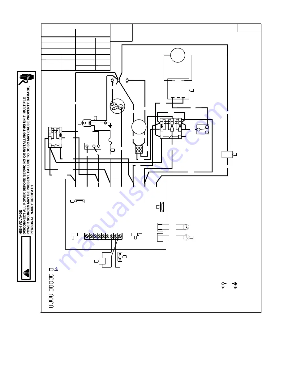
Maytag Amana NTE07A A3A Series Service Instructions Manual Download Page 70

70

PTC and PTH

(Power Door - Two Stage Heat)

SCHEMATICS

Wiring is subject to change, always refer to the wiring diagram on the unit for the most up-to-date wiring.

WA

R

N

IN

G

R

C

S

RD13

YL10

F

C

H

BR35

BR34

RD33

RIBBED

WIRE

GN

2

  RIBBED WIRE MUST BE CONNECTED AS SHOWN

NOTES:

      WARNING: DISCONNECT POWER BEFORE SERVICING. WIRING

   TO UNIT MUST BE PROPERLY POLARIZED (FOR 265V) AND GROUNDED.

REV

VALVE

SOLENOID

RD17

BK19

WIRING DIAGRAM

11179501

GN1

CONTROL

PANEL

CHASSIS

3

BR14

WH15

ON HEAT PUMP MODELS ONLY.

ON UNITS WITH REMOTE WALL MOUNTED TEMPERATURE SENSOR.

ON UNITS WITH FRONT DESK CONTROL SWITCH.

3

COMP

   OD

FAN/COMP

   CAP

REMOTE
TEMPERATURE
SENSOR

FRONT
DESK

SWITCH

4

HEAT PUMP W/AUXILLARY

ELECTRIC HEAT

CONNECT

R TO:

-----

G, Y/W1

G,B,Y/W1

G, W2

FUNCTION

OFF

COOL

1ST STAGE
HEAT
2ND STAGE
HEAT

COOLING UNIT

W/ELECTRIC HEAT

CONNECT

R TO:

G, Y/W1

G,B,Y/W1*

OR

G, W2

FUNCTION

COOL

1ST STAGE
ANTICIPATOR
CURRENT: .1
2ND STAGE
ANTICIPATOR
CURRENT: .2

ELECTRIC

 HEATER

BK20

OFF

-----

5

REMOTE THERMOSTAT OPERATION

1

SWITCHOVER

FLOODBACK
PROTECTOR

FAN

MOTOR

LINE 1

INDOOR

SWITCH

OD TUBE

OUTDOOR

SWITCH

REMOTE/STANDARD

  THERMOSTAT

    CONTROL

ON      OFF

   MASTER

   SWITCH

24 VAC

ID TUBE

24 VAC

C R G W2Y/

W1 B RS FD RC

HEATER HEATER LINE 2

COMP FAN HIGH FAN LOWR-VALVE

BK30

BK30

BK40

BK40

BK18

6

VT12

BK18 ON LINE 2 WITH FUSE SHOWN CONNECTED FOR 265V. FOR 230V, CONNECTB

   POWER CORD TO LINE 2.

REMOVE FOR 265V APPLICATIONS.
REMOVE FOR NON-HEAT PUMP APPLICATIONS.

HEAT

8

7

9

  FOR REMOTE OPERATION, SET SWITCH TO REMOTE POSITION

FUSE

1

2

3

4

5

6

7

8

9

10

IF SUPPLY VOLTAGE IS 208V MOVE 240V LEAD TO 208V TAP ON TRANSFORMER.
265V TRANSFORMER IS NOT SHOWN.

A

1
3

5

B

2
4

6

V T 1 9

2   S T G   H T

V T 2 0

2   S T G   H T

V T 1 8

2 STG HT

V T 1 7

2  

S T G  

H T

B R 3 6

2   S T G   H T

A

1

3

5

B

2

4

6

7

8

9

TRANSFORMER

Line

240

208

CO

M

Lo
ad

POWER

VENT

MOTOR

2

3

1

BU2
(PV)

BK12 

(PV)

BK11

(PV)

BK16

BK17

(PV)

BU4
(PV)

RD14

(PV)

BU15

(PV)

BU10

(PV)

WH8 

(PV)

BU9
(PV)

ON/OFF

SWITCH

TERMINAL

BOARD

POWER VENT

RELAY

10

G

FAN

FAN

G

Summary of Contents for Amana NTE07A A3A Series

Page 1: ...any L P Houston TX All rights reserved Package Terminal AirConditioners Heat Pumps This manual is to be used by qualified professionally trained HVAC technicians only Goodman does not assume any respo...

Page 2: ...RTANT INFORMATION WARNING GOODMAN WILL NOT BE RESPONSIBLE FOR ANY INJURY OR PROPERTY DAMAGE ARISING FROM IMPROPER SERVICE OR SERVICE PROCEDURES IF YOU INSTALL OR PERFORM SERVICE ON THIS UNIT YOU ASSUM...

Page 3: ...ct For further assistance please contact CONSUMERINFORMATIONLINE AMANA BRANDPRODUCTSTOLLFREE 1 877 254 4729 U S only email us at hac consumer affairs amanahvac com fax us at 931 438 4362 Not a technic...

Page 4: ...lab Cond Coil Unit D Conensated Disposal Pump C PAC 20 B Bent Condenser Coil Unit F H B D EER PAC 20 C Sound Reduction G H J E w B Design Series D 5 16 Slab Cond Coil Unit H Hydronic F EER w B Design...

Page 5: ...sion Model Type Voltage E Cooler 3 230 208 1 60 P Heat Pump 4 265 1 60 Option Code 07 7 000 Btuh A Standard Model 09 9 000 Btuh C Seacoast Model 12 12 000 Btuh 15 15 000 Btuh Electric Heat 25 2 5 kW D...

Page 6: ...4 7 7 CFM HIGH 220 215 220 220 215 220 290 270 290 325 315 325 LOW 175 155 175 175 155 175 220 190 220 250 220 250 HIGH 235 230 235 235 230 235 310 290 310 345 335 345 LOW 185 165 185 185 165 185 235...

Page 7: ...0 9 300 9 200 9 300 11 600 11 400 14 400 14 100 14 400 47 6 500 6 400 6 500 8 400 8 300 8 400 10 800 10 600 13 400 13 100 13 400 Rating Point COP 3 3 3 3 3 3 32 3 2 3 2 3 1 3 1 2 9 2 9 2 9 452 5 800 5...

Page 8: ...65 65 65 70 70 70 70 Dehumidification pints hr 1 6 1 6 2 6 2 6 3 5 3 5 4 4 4 4 Net Weight 95 90 100 100 110 110 115 115 Shipping Weight approx lbs 110 110 115 115 125 125 130 130 Cool Wet Coil COOLIN...

Page 9: ...IT WITHOUT ELECTRIC HEATER Minimum Circuit Ampacity 2 4 4 0 3 6 5 1 4 4 6 4 5 7 8 8 7 7 CFM HIGH 245 240 245 245 240 245 325 315 325 325 315 325 LOW 220 205 220 220 205 220 250 229 250 250 220 250 HIG...

Page 10: ...U h models HEAT PERFORMANCE ELECTRIC HEAT ELECTRIC DATA ALL BTUH SIZES ALL MODELS Nominal Heating BTUH Number of Stages Electric Heater Size kW Voltage Total Watts Total Amps Minimum Ampacity 1 Overcu...

Page 11: ...3 6 9 5 9 Watts 655 640 655 830 810 830 1 165 1 145 1 165 1 540 1 515 1 540 EER 10 8 10 8 11 11 10 2 10 2 8 9 8 9 UNIT WITHOUT ELECTRIC HEATER Minimum Circuit Ampacity 2 4 4 0 3 6 5 1 4 4 6 4 5 7 8 4...

Page 12: ...vent kit Actual vent CFM performance will vary due to application and installation conditions NOTES Model 1 7 9 10 12 PTC 094D PTC 124C AM PTC 154D Voltage 1 3 11 265 265 265 Capacity BUTH 9100 11 60...

Page 13: ...lampsfor12 000and15 000Btuhmodels subtract0 2ampsforPT07 09 9 Refrigerant used in all systems is R 22 10 All units meet or exceed ASHRAE 90 1 standards 11 All units less than 250 volts have a Leak Cur...

Page 14: ...000 9 900 9 700 12 200 11 700 12 800 12 600 9 800 12 200 57 6 900 6 700 9 400 9 200 11 500 11 000 12 100 11 900 9 300 11 500 52 6 500 6 300 8 800 8 600 10 800 10 300 11 400 11 200 8 700 10 800 47 6 20...

Page 15: ...rcurrent protection on 265 volt models must be cartridge style time delay fuses included and factory installed on chassis 5 Heating capacity and efficiency is based on unit operation without condensat...

Page 16: ...arances and Mini mum Interior and Exterior Projections Figures as well as Minimum Clearances and Projections table for details If installed in a concrete or masonry wall a lintel must be provided in t...

Page 17: ...xten sion cords must not be used with the unit See the note on Wall Sleeve Dimensions Figure 42 1 4 1075 mm Minimum 16 1 4 415 mm Mini mum Dimension B in Table 1 Minimum Wall Opening Dimensions When 2...

Page 18: ...5 Two holes will need to be drilled in both sides of the wall sleeve for mounting into the wall Drill holes of proper size and in the proper location so the screws will engage into strong supporting m...

Page 19: ...damage the compressor and void the warranty Front Mounting Holes Two mounting holes are provided to give the owner the option of securing the front to the chassis The mounting holes are located behin...

Page 20: ...Switch The table below describes the unit function corresponding to the various mode switch settings Switch Position Unit Function OFF Unit is completely off However before servicing open all disconn...

Page 21: ...t Connections Y W1 W2 W1 W2 Control Board Connections Thermostat Connections EH LS Y R Control Board Connections Thermostat Connections 14 Pin Connector B EH LS X1 B Y R Control Board Connections Ther...

Page 22: ...FD and RC terminals or FD1 and FD2 provide control in puts for a front desk switch Shorting across these two termi nals will disable unit operation The only control function which will remain active...

Page 23: ...ll vary slightly 64 F 68 F 71 F 75 F 82 F 85 F 87 F 87 F 63 F 63 F 66 F 69 F 76 F 79 F 83 F 86 F Low End Cooling Limits High End Heating Limits Temperature Limiter Settings The temperature limits are...

Page 24: ...icates operation warnings This light usually indicates that either the filter or coils need cleaning Please refer to the Maintenance and Cleaning section for the proper cleaning procedure If this ligh...

Page 25: ...t so that the backside is accessible 3 Remove the four nuts which secure the discharge air grille to the cabinet front 4 Rotate the grille 180 end for end 5 Reinstall the nuts securing the discharge a...

Page 26: ...Pull the inlet grille forward from the top of the grille to access screw s FRONT MOUNTING HOLE 3 Remove cabinet front from chassis by tilting the bottom of the front forward lifting slightly up and fo...

Page 27: ...s included into the back of the thermostat Terminals are marked and for po larity DOOR MAGNET INSTALLATION Mount the door magnet holder on the front of the door where it will be as close as possible t...

Page 28: ...DD01 mountingplate The following figures show the magnet 1 2 from the sensor mounting plate in different slot positions A B C POSITION A Place magnet in Position A in instances when the door trim exte...

Page 29: ...ounting plate 7 Configure the device or devices that were bound See the next section for configuration choices NOTE If a wireless device is replaced or added all devices including those previously bou...

Page 30: ...you will see 25 for v2 5 Other software versions may have different factory setback defaults Contact your PTAC representative to determine factory default settings WARNING USEOFSETBACKTEMPERATURES Don...

Page 31: ...ANY MODIFICATION OR REPAIRS TO THE INTERNAL COMPONENTS OR TO THE ANTENNA CONFIGURATION OF THE NOTE To comply with FCC RF exposure requirements in section 1 1307 a minimum separation distance of 20cm 8...

Page 32: ...maximum heating set point 8 Mating thermostat has a B terminal 0 Mating thermostat has an O terminal 0 Not Active A Active c3 Unrented Cooling Temperature 45 95 79 Select temperature between 45 and 9...

Page 33: ...following procedure is used to remove the intake filter 1 Open the intake grille by grasping the top intake louver 2 Pull the intake grille open 3 Slide filter upward and remove 4 Clean filter with va...

Page 34: ...eve are properly sealed The wall sleeve s level should also be rechecked Proper leveling for most installations are a bubble tilt to the outside and level from right to left Contact your sales person...

Page 35: ...unds Water is picked up and distributed over the coil This improves the efficiency and helps with water removal Water Dripping Water will collect in the base pan during high humidity days This can cau...

Page 36: ...ain on until the Thermistor senses a temperature of 43 F OPERATIONS Fan Advance Delay The advance feature will allow the fan to start six seconds prior to the compressor starting in either cooling or...

Page 37: ...lure Replace Indoor Coil Thermister 4 Flashes Mode Switch Failure Replace Board 5 Flashes Thermostat Control Replace Board 6 Flashes Thermostat Input Failure Replace Thermostat or Correct Wiring 8 Fla...

Page 38: ...occupant unit operation On Control is configured to respond to a wired thermostat Y N No action if a wired thermostat is being used Otherwise see Configuration Settings Indoor Ambient Thermistor reads...

Page 39: ...aled System Air Conditioner Condenser Compressor Evaporator Capillary Tube Process Strainer Suction Line Discharge Line Capillary Tube Check Valve Open Reversing Valve D i s c a r e i e Suction Line R...

Page 40: ...40 i r i Refrigeration Sealed System Heat Pump Heat Pump Mode OPERATIONS REFRIGERATION SEALED SYSTEM...

Page 41: ...ygen from moisture plus normal compressor and motor heat reacts chemically with the refrigerant and oil to form corrosive hydrochloric and hydrofluoric acids These ac ids contribute to the breakdown o...

Page 42: ...on the charging cylinder closed open the manifold valve to the cylinder 6 Evacuate the system to at least 29 inches gauge before opening valve to thermocouple vacuum gauge 7 Continue to evacuate to a...

Page 43: ...sting Cooling Test The following temperature must be recorded for the cooling performance test A Dry bulb temperature of return air at conditioner Locate thermometer as illustrated B Dry bulb temperat...

Page 44: ...amps recorded should fall within the minimum and maximum watts amps listed on these charts EXAMPLE Assume that a PTH15 230 208V with 3 5 kW elec tric heater is under test 1 Supply voltage as recorded...

Page 45: ...0 565 635 725 805 1015 1110 1390 1505 65 560 630 720 800 1010 1105 1385 1500 60 550 620 710 790 1000 1095 1370 1485 55 540 610 700 780 990 1085 1350 1465 85 525 600 680 755 960 1055 1285 1400 80 530 6...

Page 46: ...Indoor Coil T Temperature Across Indoor Coil T 70 75 80 85 90 Outside Coil Dry Bulb F Room Wet Bulb F PTH073 PTH074 PTH093 PTH094 PTH123 PTH124 PTH153 PTH154 Min Max Min Max Min Max Min Max 85 1 3 2...

Page 47: ...40 Outside Coil Dry Bulb F Room Wet Bulb F M odel C ond Inlet A ir Temperature F Min Max Min Max Min Max Min Max Min Max Min Max Min Max Min Max 1 00 2 8 3 0 2 3 2 5 3 5 3 9 2 7 2 9 4 8 5 4 4 0 4 4 6...

Page 48: ...27 26 31 29 34 75 18 23 24 28 27 32 30 35 70 19 24 25 29 28 33 31 36 65 20 25 26 30 29 34 32 37 85 14 18 19 24 23 27 28 32 80 15 19 20 25 24 28 29 33 75 16 20 21 26 25 29 30 34 70 17 21 22 27 26 30 31...

Page 49: ...f cleaning the filter or coils does not clear the status code or the code indicates that servicer should be called DIAGNOSTIC STATUS REPORT MODE To enter Diagnostic Status Report mode press and hold t...

Page 50: ...N Replace black Indoor Ambient Thermistor F4 Indoor Coil Thermistor either above or below operating tolerances N Y Replace Red Indoor Coil Thremistor F5 Wireless Thermostat failure N Y Attempt to reb...

Page 51: ...d Compressor Test Motor Windings S 17 Compressor Stuck Use Test Cord S 17 Open Control Circuit Test Control Circuit with Voltmeter S 1 Low Voltage Test Voltage S 1 Faulty Evap or Cond Fan Motor Repair...

Page 52: ...wo screws securing the top screen to the evaporator assembly Be sure to slide the top of the screen between the top flange and chassis when reassembling 8 Remove the two screws securing the heater ass...

Page 53: ...6 Heater Assembly All heaters produced May of 2004 have a manual reset limit 5 All heater assembly components are now accessible 6 All heaters manufactured after May of 2004 have a manual reset limit...

Page 54: ...e Temperature Characteristic 0 20000 40000 60000 80000 100000 120000 140000 160000 180000 0 10 20 30 40 50 60 70 80 90 100 110 120 130 140 150 160 170 Temperature deg F Resistance ohms THERMISTOR RESI...

Page 55: ...he capacitor mounting clamp to the center partition Remove the capacitor Resistance Check WARNING Discharge capacitor and remove wire leads WARNING DISCHARGE CAPACITOR THROUGH A 20 TO 30 OHM RESISTOR...

Page 56: ...e the brace 12 Remove the two screws securing the condenser air baffle to the center partition Remove the brace 13 Remove all screws from the sides of the outdoor coil se curing the shroud to the coil...

Page 57: ...no power wire a test cord to line voltage L1 L2 NOTE The wire size of the test cord must equal the line size and the fuses in the test line must be of the proper size and type Test Cord Connections C...

Page 58: ...al 4 After all the refrigerant has been recovered from the system remove bottom of strainer by unbrazing the strainer from the condenser elbow Hold the strainer with a pair of pliers while heating up...

Page 59: ...test continuous replace it If the valve is inoperative replace SOUND LEVEL Noise complaints are frequently caused by a faulty installation or by the customer s lack of knowledge and information Sourc...

Page 60: ...anel cover Tilt the control panel for ward to gain access to the wires 4 Remove the power cord clamp located near the bottom right of the chassis Control Panel Power Incoming Power Opening Right Side...

Page 61: ...OOR COIL 1 Remove the chassis from the wall sleeve 2 After capturing the refrigerant from the system debraze the inlet and discharge tubing from the outdoor coil 3 Remove all screws from the sides of...

Page 62: ...E SENSOR FRONT DESK SWITCH 4 1ST STAGE ANTICIPATOR CURRENT 1 2ND STAGE ANTICIPATOR CURRENT 2 ELECTRIC HEATER BK20 5 REMOTE THERMOSTAT OPERATION 1 SWITCHOVER FLOODBACK PROTECTOR FAN MOTOR LINE 1 INDOOR...

Page 63: ...WIRING TO UNIT MUST BE PROPERLY POLARIZED FOR 265V AND GROUNDED REV VALVE SOLENOID RD17 BK19 GN1 CONTROL PANEL CHASSIS 3 BR14 WH15 ON HEAT PUMP MODELS ONLY 3 COMP OD FAN COMP CAP ELECTRIC HEATER BK20...

Page 64: ...MUST BE CONNECTED AS SHOWN NOTES WARNING DISCONNECT POWER BEFORE SERVICING WIRING TO UNIT MUST BE PROPERLY POLARIZED FOR 265V AND GROUNDED REV VALVE SOLENOID BK19 WIRING DIAGRAM 11179901 GN1 CONTROL...

Page 65: ...D STAGE ANTICIPATOR CURRENT 2 ELECTRIC HEATER BK20 5 REMOTE THERMOSTAT OPERATION 1 SWITCHOVER FLOODBACK PROTECTOR FAN MOTOR LINE 1 INDOOR SWITCH OD TUBE OUTDOOR SWITCH REMOTE STANDARD THERMOSTAT CONTR...

Page 66: ...HERMOSTAT OPERATION 1 SWITCHOVER FLOODBACK PROTECTOR FAN MOTOR LINE 1 INDOOR SWITCH OD TUBE OUTDOOR SWITCH REMOTE STANDARD THERMOSTAT CONTROL ON OFF MASTER SWITCH 24 VAC ID TUBE 24 VAC C R G W2Y W1 B...

Page 67: ...LOAD LINE FLOODBACK PROTECTOR FAN MOTOR MOTOR LINE 1 INDOOR OD TUBE OUTDOOR REMOTE STANDARD THERMOSTAT CONTROL ON OFF MASTER 24 VAC ID TUBE 24 VAC C R G B RS FD RC HEATER HEATER LINE 2 COMP FAN HIGH...

Page 68: ...UTDOOR REMOTE STANDARD THERMOSTAT CONTROL ON OFF MASTER 24 VAC ID TUBE 24 VAC C R G B RS FD RC HEATER HEATER LINE 2 COMP FAN HIGH R VALVE BK30 BK30 BK40 BK40 BK18 VT12 7 REMOVE FOR 265V APPLICATIONS 8...

Page 69: ...REMOTE THERMOSTAT OPERATION 1 SWITCHOVER FLOODBACK PROTECTOR FAN MOTOR LINE 1 INDOOR SWITCH OD TUBE OUTDOOR SWITCH REMOTE STANDARD THERMOSTAT CONTROL ON OFF MASTER SWITCH 24 VAC ID TUBE 24 VAC C R G...

Page 70: ...ANTICIPATOR CURRENT 1 2ND STAGE ANTICIPATOR CURRENT 2 ELECTRIC HEATER BK20 OFF 5 REMOTE THERMOSTAT OPERATION 1 SWITCHOVER FLOODBACK PROTECTOR FAN MOTOR LINE 1 INDOOR SWITCH OD TUBE OUTDOOR SWITCH REM...

Page 71: ...1ST STAGE ANTICIPATOR CURRENT 1 2ND STAGE ANTICIPATOR CURRENT 2 ELECTRIC HEATER OFF 5 REMOTE THERMOSTAT OPERATION 1 SWITCHOVER FLOODBACK PROTECTOR FAN MOTOR LINE 1 INDOOR SWITCH OD TUBE OUTDOOR SWITC...

Page 72: ...ICIPATOR CURRENT 1 2ND STAGE ANTICIPATOR CURRENT 2 ELECTRIC HEATER OFF 5 REMOTE THERMOSTAT OPERATION 1 SWITCHOVER FLOODBACK PROTECTOR FAN MOTOR LINE 1 INDOOR SWITCH OD TUBE OUTDOOR SWITCH REMOTE STAND...

Page 73: ...L AT FACTORY HEAT PUMP W AUXILIARY ELECTRIC HEAT CONNECT R TO G Y W1 G B Y W1 G W2 FUNCTION OFF COOL 1ST STAGE HEAT 2ND STAGE HEAT COOLING UNIT W ELECTRIC HEAT CONNECT R TO G Y W1 G W2 OR G B Y W1 FUN...

Page 74: ...74 PTC and PTH C Models Condensate Pump with Power Vent Two Stage Heat SCHEMATICS Wiring is subject to change always refer to the wiring diagram on the unit for the most up to date wiring WARNING...

Page 75: ...ONT OD TUBE COMP 7 REMOVE FOR 265V APPLICATIONS 8 REMOVE FOR NON HEAT PUMP APPLICATIONS HEAT PUMP W AUXILIARY OFF OR OFF ON A STRAIGHT N O YL13 Hydronic SCHEMATICS Wiring is subject to change always r...

Page 76: ...FF OR OFF ON A STRAIGHT N O YL13 GN COMP FRONT OD TUBE COMP PV PV PV PV PV PV PV PV PV PV PV CONNECT BU21 IF USING N C VALVE Hydronic Condensate Pump with Power Vent or Power Door SCHEMATICS Wiring is...

Page 77: ...OWN CONNECTED FOR 265V FOR 230V 115V CONNECT FOR REMOTE OPERATION SEE CONFIGURATION CHART IF SUPPLY VOLTAGE IS 208V 230V USE THE 230V TAP ON TRANSFORMER FOR CONTINUOS FAN OPERATION SEE CONFIGURATION C...

Page 78: ...ON A STRAIGHT COOL UNIT USE COPPER CONDUCTORS ONLY FRONT DESK SWITCH 4 1ST STAGE ANTICIPATOR CURRENT 1 2ND STAGE ANTICIPATOR CURRENT 1 240 208 COM LOAD LINE TR AN SFO RM ER 8 GY21 GY22 BK37 BK18 5 7...

Page 79: ...GE FACTORY OR FIELD LOW VOLTAGE FACTORY OR FIELD 3 GY22 GY21 265 230 4 SWITCH FRONT RD33 PV RD17 PV PV RD14 BLOCK 3 6 9 8 5 2 7 4 1 PV 6 PV PV WH7 PV PV PV PV PV WH8 1 2 3 SWITCH VT12 5 MOTOR FAN 1 20...

Reviews: