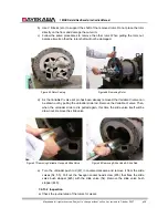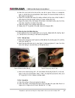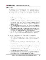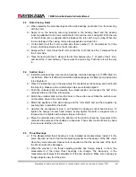
160GR Natural Gas Booster Instruction Manual
Mayekawa all rights reserved. Subject to change without notice. Lat revised in October 2007
p.40
8. Re-assembly
When the inspections and repair of each part has been completed, proceed to the process of
re-assembling the compressor. Reassembling process is essentially carried out in reverse
order of disassembly. Use the same tools used for disassembly and pay attentions for safety.
The tools to be used should be thoroughly cleaned. The parts to be assembled should be
washed and lubricated before assembled.
8.1
Bearing Head and Main Bearing
a
)
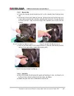
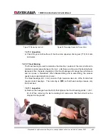
Before installing the main bearing, the labyrinth seals and the lubrication rings need to
be installed.
b
)
First, install the labyrinth seals. Do not forget
“
O
”
rings will be inserted in the outer rim. If
the labyrinth seals and the
“
O
”
rings cannot be installed together, install the
“
O
”
rings in
the bearing head first and then the labyrinth seals. Make sure the labyrinth seals are
inserted all the way to the back. If the seals cannot be inserted all the way, they may be
chewing the
“
O
”
rings.
c
)
Then, install the lubrication rings. The labyrinth seals, which should be installed in the
prior step, have the stopper pin. Install the lubrication rings to match the pin holes on the
seals.
d
)
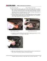
The main bearing is fitted in the gap. If the bearings are inserted straight to the housing,
they should be inserted quite smoothly. When the bearings do not go in smoothly, they
are not straight to the housing. Use a pad, and tap them to straighten them.
e
)
Apply some oil to the gasket that is to be installed between the bearing head and the
rotor casing. The gasket is not symmetric. Make sure to attach it in the right direction.
8.2
Rotor Casing, Unloader Slide Valve, Variable Vi Slide Valve, Bearing Head
a
)
Unloader Slide Valve
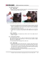
Attach the
“
O
”
ring (523) to the slide valve end plate. Install the end plate to the slide
valve. Install the unloader slide rod in the unload slide valve by screwing it all the way in
clockwise.
b
)
Rotor Casing
Clean oil line, and do not forget to plug them. Install the unloader slide valve in the rotor
casing. Check the movement in the shaft direction. Likewise, check the movement of the
Variable Vi slide valve.
c
)
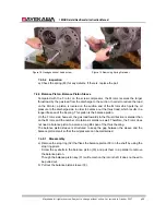
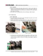
Install the rotor casing the bearing head. Hammer the alignment pins in, and insert the
hexagon socket head screws. To tighten the hexagon socket head screws, evenly
tighten the bolts in diagonal. Use a torque wrench to tighten with a proper torque in the
end. A few bolts on the bottom are to be tightened later.
d
)
Install the unloader slide valve and the unloader slide rod, which are already put together,
in the rotor casing. Attach the Variable Vi slide valve.
e
)
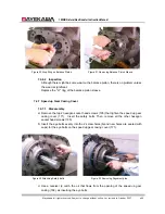
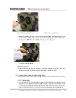
If the bearing head gasket hangs out to the interior of the rotor casing, cut the gasket off
with a knife (etc.). When the gasket is left there, it can be caught between the edge of the
rotor and the bearing head, which prevents the proper thrust adjustment.

