160GR Natural Gas Booster Instruction Manual
Mayekawa all rights reserved. Subject to change without notice. Lat revised in October 2007
p.25
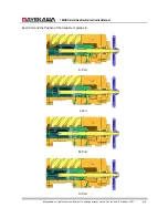
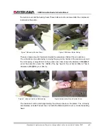
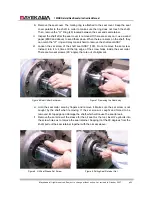
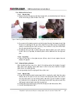
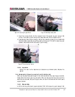
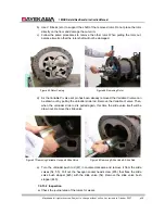
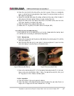
Figure 10 Removing Unloader cover bolt
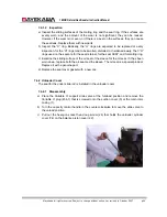
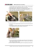
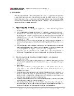
Figure 11 Removing
Variable Vi Support pin
(with Suction Cover on)
d
)
The
“
O
”
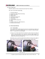
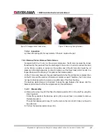
ring (82) to seal the unloader push rod (67) is installed on the unloader cover.
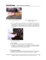
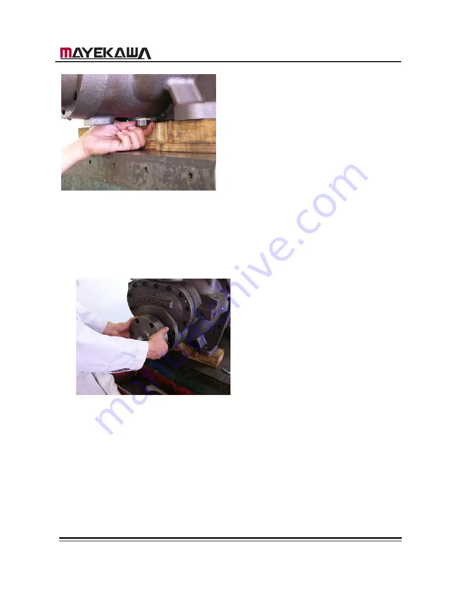
When pulling the unloader cover out, keep the hole of the cover parallel to the
unloader slide rod. Forcing the angled cover to be pulled out can damage the shaft.
Use a receiver for the residual oil that may flow from the gap in the cover flange in this
process.
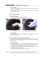
Figure 12 Removing Unload Cover
7.4.2.2 Inspection
a
)
Check of there is a wear in the seal area of the unloader slide rod.
b
)
Inspect the “O” ring (82). Inspect the “O” ring. Basically, the “O” rings are expected to
be replaced at every inspection, for the “O” rings tend to be swollen, distorted, or
hardened easily, and such conditions will cause a leak.
7.4.3 Unloader Thrust Bearing
The Unloader thrust bearing is the bearing that decides the position of the unloader slide
rod and receives the thrust load that is created on the slide valve from unloading.

