160GR Natural Gas Booster Instruction Manual
Mayekawa all rights reserved. Subject to change without notice. Lat revised in October 2007
p.2
Contents
1. Introduction .......................................................................................................................................... 4
2. Capacity Control Procedures ............................................................................................................... 4
3. Variable Vi Structure ............................................................................................................................ 4
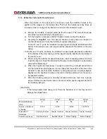
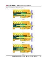
3.1.1 When the position of the current port is known
...................................................................... 5
3.1.2 When the Current Port is not known
.................................................................................... 10
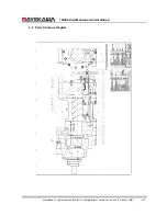
4. Parts Expanded View ........................................................................................................................ 13
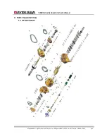
4-1 160GR Standard
................................................................................................................. 13
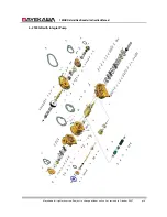
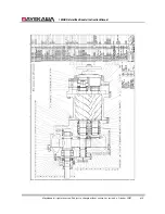
4-2
160GR with Integral Pump
.................................................................................................. 14
4-3 Parts Structure Diagram
...................................................................................................... 15
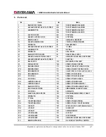
5. Parts List............................................................................................................................................ 17
6. Outer Dimension ................................................................................................................................ 19
7. Disassembly ...................................................................................................................................... 20
Removing the Compressor
.............................................................................................................. 20
7.1
Interior Gas Recovery
.................................................................................................... 20
7.2
Removing the connecting parts
...................................................................................... 20
7.3
Suspending and Transferring the Compressor
............................................................... 20
7.4.1
Mechanical Shaft Seal
.................................................................................................... 22
7.4.2
Unloader Cover
.............................................................................................................. 24
7.4.3
Unloader Thrust Bearing
................................................................................................ 25
7.4.4
Balance Piston Cover
..................................................................................................... 27
7.4.5
Unloader Spring Retainer
............................................................................................... 27
7.4.6
Balance Piston, Balance Piston Sleeve
.......................................................................... 28
7.4.7
Speed up Gear Casing Cover
........................................................................................ 29
7.4.8
Speed up gear casing
.................................................................................................... 30
7.4.9
Disassembly of speed up gear parts on the driving side
................................................ 31
7.4.10
Spindle Roller Bearing
.................................................................................................... 33
7.4.11
Disassembly of the speed up gear on the driven side
.................................................... 33
7.4.12
Thrust Bearing
................................................................................................................ 34
7.4.12
Suction Cover
................................................................................................................. 36
7.4.13
Rotor, Rotor Casing, Variable Vi Slide Valve
.................................................................. 37
7.4.14
Bearing Head and Main Bearing
.................................................................................... 39
8. Re-assembly ...................................................................................................................................... 40
8.1
Bearing Head and Main Bearing
......................................................................................... 40
8.2
Rotor Casing, Unloader Slide Valve, Variable Vi Slide Valve, Bearing Head
....................... 40
8.3
Rotor Casing, Rotor
............................................................................................................ 41
8.4
Suction Cover
...................................................................................................................... 41
8.5
Thrust Bearings
................................................................................................................... 41
8.5
Installation of the driven side speed up gear
....................................................................... 42
8.6
Spindle Roller Bearings
....................................................................................................... 43
8.7
Building the Driving Side speed up Gear
............................................................................ 43
8.8
Installation of speed up Gear Casing
.................................................................................. 43


