160GR Natural Gas Booster Instruction Manual
Mayekawa all rights reserved. Subject to change without notice. Lat revised in October 2007
p.42
c
)
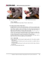
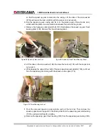
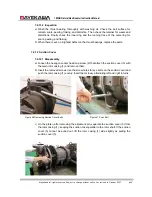
First, install the washer and the thrust adjusting washer, and proceed to the thrust
bearings. Install the thrust bearings in the way that the tip of the
“
V
”
mark faces the rotor
side. When the thrust bearings are facing the wrong way, the measurement of the
outer-ring and the inner-ring change. The inaccuracy in the measurement will change
the end clearance from the value before the disassembly.
d
)
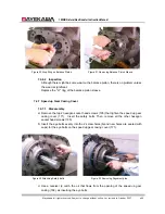
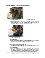
Install the thrust washer and the lock washer. Insert the packing (
はさみ板
), and fix the
inner-ring of the thrust bearing with the rotor shaft by the lock nut. If the thrust bearing
has been replaced, tighten the lock nut slowly to make sure there is an end clearance.
With a brand-new bearing, there may be a little difference in the measurements of the
outer-ring and the inner-ring which will cancel the end clearance. Tightening the nuts on
the new bearing will push the ball towards the moving part and will leave pressure traces.
When there is no end clearance, replace the thrust adjusting washer with one whose
width is thicker, or insert a shim to adjust the measurement.
e
)
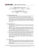
Tighten the lock nuts with the torque specified below. Match the position of the groove on
the lock nut and that of the tabs on the lock washer.
f
)
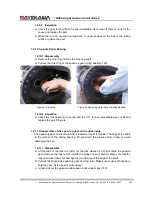
With the inner-ring of the thrust bearing attached with the rotor shaft, push the tip of the
rotor
’
s discharge side towards the discharge side. Push it to the position where there is
no end clearance (0).
g
)
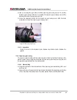
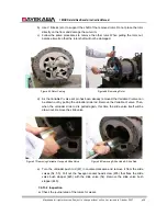
With the rotor moved to the discharge side, place the tip of the dial indicator on the top of
the rotor suction, and set the needle at
“
0.
”
Install the thrust cramp-2. Get ready to install
the thrust cramp-1.
h
)
With bolts, tightens the bearing cramps evenly with the torque specified below. This
process will create an opening in the top of the rotor discharge side, as the thrust
bearings are pushed by the bearing cramps.
i
)
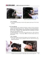
Read the value on the dial indicator at this time. This value indicates the moving distance
of the rotor and also the end clearance. When the end clearance is beyond or below the
range specified below, some adjustment is required. To adjust the end clearance, read
9.5.1 of this manual.
j
)
Having adjusted the end clearance, turn the M rotor by hand to make sure the M rotor
turns.
k
)
Likewise, thrust adjustment should be done on the F rotor.
l
)
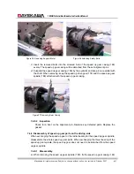
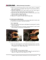
Place the dial indicator on the journal area of the M rotor, and let the shaft rotate to check
the vibration of the shaft. The allowable vibration is within 0.33mm.
When the vibration is beyond the allowable range, loosen the lock nut. When tightening
the lock nut again, slightly change the position of the tabs where the lock nut wrench is
laid. If the vibration is still larger than the allowable value, the adjusting washer, the
alignment of the spacer, foreign objects among the arts can be the cause. Disassemble
the parts again, and check for the cause. Also, it could be because of the misplacement
of the V mark on the bearing, or the direction of the adjusting washer and spacer when
installed.
m
)
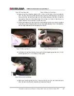
At last, fold the tabs of the lock washer.
8.5
Installation of the driven side speed up gear
a
)
Install the speed up gear in the M rotor. First, install the gear spacer on the driven side
and the driven side speed up gear key.

