160GR Natural Gas Booster Instruction Manual
Mayekawa all rights reserved. Subject to change without notice. Lat revised in October 2007
p.34
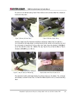
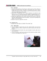
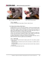
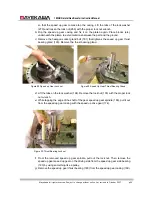
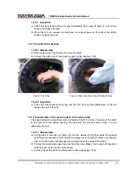
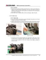
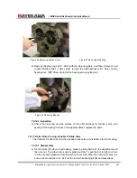
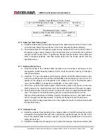
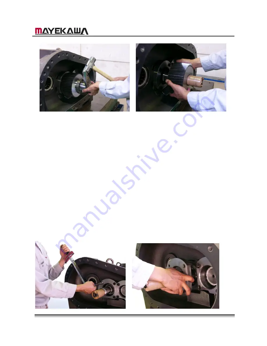
Figure 33 Removing Lock nut
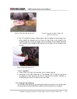
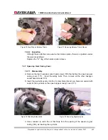
Figure 34 Removing Speed Up Driven Gear
7.4.11.2 Inspection
a
)
Check the gear tooth surface of the drive side speed up driven gear (179) for scars
and wears.
7.4.12 Thrust Bearing
The thrust bearing is used to determine the direction / position of the rotor shaft and to
maintain a certain space between the rotor
’
s discharge end face and the bearing head.
Because of this, the parts integration of the thrust bearings will change the performance
and can cause a breakdown. When disassembling and re-assembling, the process
needs to be conducted with much care.
The thrust bearings (38-1, 38-2) consist of high precision class etc. of the front-to-front
angular contact bearings. The outer-ring is
隙間
so that these bearings receive only
the thrust load.
7.4.11.1 Inspection
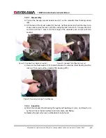
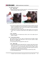
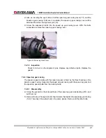
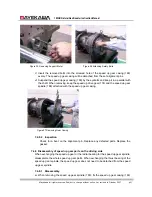
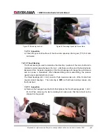
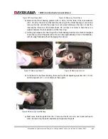
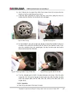
a) Remove the hexagon head bolt (45) that tightens the thrust bearing glands 1 (43-1,
43-3). When removing the last remaining bolt, make sure that the bolt will not be
dropped on the ground.

