background image

  D
 GB
  F
  E

1

96031-11.2011-DGbFEI

GEA Refrigeration Technologies /


GEA Bock

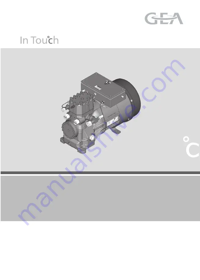
HAX2/70-4 CO2 T

HAX2/90-4 CO2 T

HAX2/110-4 CO2 T

HAX2/130-4 CO2 T

Assembly instructions

Summary of Contents for HAX2 CO2 T Series

Page 1: ...D GB F E 1 96031 11 2011 DGbFEI GEA Refrigeration Technologies GEA Bock HAX2 70 4 CO2 T HAX2 90 4 CO2 T HAX2 110 4 CO2 T HAX2 130 4 CO2 T Assembly instructions ...

Page 2: ... the compressor can result in serious or fatal injury Observe the safety instructions contained in these instructions These instructions must be passed onto the end customer along with the unit in which the compres sor is installed GEA Bock GmbH 72636 Frickenhausen GEA Bock GmbH Benzstraße 7 72636 Frickenhausen Germany Telephone 49 7022 9454 0 Fax 49 7022 9454 137 mail bock de www bock de Manufact...

Page 3: ...l connection 12 5 1 Information for contactor and motor contactor selection 5 2 Standad motor designed for direct or part winding start 5 3 Maine line wiring diagram for part winding 5 4 Electronic trigger unit MP 10 5 5 Connection of the electronic trigger unit MP 10 5 6 Functional test of the electronic trigger unit MP 10 5 7 Oil sump heater 5 8 Fan motor 6 Commissioning 18 6 1 Preparations for ...

Page 4: ...ed machines and therefore require particular caution and care in handling Risk of burns Depending on the operating conditions surface temperatures of over 60 C on the pressure side or below 0 C on the suction side can be reached The maximum permissible overpressure must not be exceeded even for testing purposes 1 1 Identification of safety instructions DANGER Indicates a dangerous situation which ...

Page 5: ...ited 1 4 Intended use WARNING The compressor may not be used in potentially explosive environments The Bock refrigerating compressor named in the title is intended for installing in a machine within the EU according to the EU Directives 2006 42 EC Machinery Directive 97 23 EC Pressure Equipment Directive and 2006 95 EC Low Voltage Directive Commissioning is only permissible if the compressor has b...

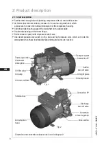
Page 6: ...e Bi directional oil pump with oil pressure relief valve One decompression valve each on the low and high pressure side which vent into the atmosphere when these inadmissibly high printing pressures are reached 2 1 Short description Discharge shut off valve Dimension and connection values can be found in Chapter 9 Fig 1 Fig 2 Connection oi level regulator Connection HP Oil sump heater Oil sight gl...

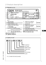
Page 7: ...rating pressure g Low pressure side HD HP max permissible operating pressure g High pressure side Observe the limits of application diagrams 50 Hz 60 Hz 6 Voltage circuit frequency 7 Nominal rotation speed 8 Displacement 9 Voltage circuit frequency 10 Nominal rotation speed 11 Displacement 12 Oil type filled at the factory 13 Terminal box protection type Electrical accessories can change the IP pr...

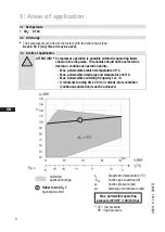
Page 8: ...y 12x h A minimum running time of 3 min steady state condition continuous operation must be achieved The compressors are filled at the factory with the following oil type Bock C 85 E only this oil may be used 3 1 Refrigerants CO2 R744 3 2 Oil charge 3 3 Limits of application Max permissible operating pressure LP HP 1 100 150 bar Unlimited application range 1 HAX2 130 4 CO2 T Applications limit 1 L...

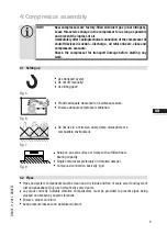
Page 9: ...Teile Nr x xxxx xxxxx x Maßstab 1 1 INFO New compressors are factory filled with inert gas 3 bar nitrogen Leave this service charge in the compressor for as long as possible and prevent the ingress of air Immediately after coolingtechnical connection of the compressor of shutoff devices in suction discharge oil return line etc close and compressors evacuate Check the compressor for transport damag...

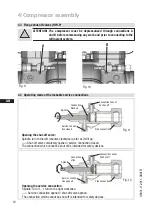
Page 10: ...he left counter clockwise as far as it will go Shut off valve completely opened service connection closed The connection which cannot be shut off is intended for safety devices Opening the service connection Spindle Turn 1 turn to the right clockwise Service connection opened shut off valve opened The connection which cannot be shut off is intended for safety devices Spindle Connection cannot be s...

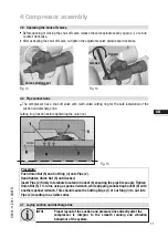
Page 11: ...e shut off valve re tighten the adjustable valve spindle seal clockwise Fig 13 Fig 14 4 7 Laying suction and discharge line INFO Proper layout of the suction and pressure lines directly after the compressor is integral to the smooth running and vibration behaviour of the system Procedure Push Union Nut 5 and Cut Ring 3 onto Pipe 2 Hand tighten Union Nut 5 until locked Insert Pipe 2 firmly into reb...

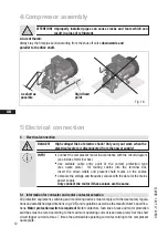
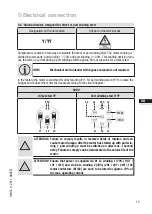
Page 12: ... possible Rigid fixed point 4 Compressor assembly ATTENTION Improperly installed pipes can cause cracks and tears which can result in a loss of refrigerant A rule of thumb Always lay the first pipe section starting from the shut off valve downwards and parallel to the drive shaft 5 1 Information for contactor and motor contactor selection All protection equipment switching and monitoring devices m...

Page 13: ...s way are suitable for direct or part winding start The motor winding is divided into two parts part winding 1 70 and part winding 2 30 This winding devision redu ces the start up current during a part winding start to approx 65 of the value for a direct start ATTENTION Failure to comply results in reversed fields of rotation and can cause motor damage After the motor has started up with part win ...

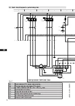
Page 14: ...afety monitor F4 Safety chain high low pressure monitoring F5 Oil differential pressure monitor B1 Release switch thermostat nderung 0 Datum Name Datum Bearb Gepr Norm 1 02 Feb 2009 Kelich 10 Feb 2010 Urspr 2 Ers 3 Ers d 4 X SS Q1 L1 L2 L3 N PE Anschlu asten Verdichter I 66 F1 1 K1 1 2 1 3 4 2 5 6 3 1U1 1V1 1W1 M Y YY M1 R1 2U1 2V1 2W1 I 33 F1 2 K2 1 2 4 3 4 5 5 6 6 PE X1 L1 L1 N N 43 43 11 12 14 ...

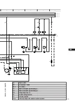
Page 15: ...ontactor part winding 2 K1T Delay relay max 1s S1 Control voltage switch E1 Oil sump heater XSS Terminal strip in the external switch cabinet PW MP10 5 6 7 B CK C MPRESS RS 8 9 Bl 1 Bl 1 M 1 M1 1 K1 9 X3 1 10 2 C1 3 F5 4 T2 N P l L P F3 M S 11 12 13 K1 P F4 14 K1 K1T K2 15 16 K1T P B1 17 18 K1 19 E1 20 L1 1 L2 1 L3 1 L1 2 N PE ...

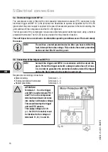
Page 16: ...rt prevention device After you have rectified the fault interrupt the mains voltage This unlocks the restart prevention device and the LEDs H1 and H2 go out Temperature monitoring connections Motor winding Terminals 1 2 Thermal protection thermostat Terminals 3 4 Restart prevention Terminals 5 6 ATTENTION Terminals 1 6 on the trigger unit MP 10 and terminals PTC 1 and PTC 2 on the compressor termi...

Page 17: ...FF OFF OFF Release the motor temperature sensor connection 1 or 2 Release the hot gas temperature sensor if installed 3 or 4 2 Restore the power supply L1 or S1 ON Function check of motor temperature sensor operational ON Function check of hot gas temperature sensor operational ON 3 Interrupt power supply again L1 or S1 OFF OFF OFF Reconnect terminals 1 or 2 and or 3 or 4 4 Restore the power suppl...

Page 18: ...g to EN 378 2 or a corresponding safety standard The pressure strength test is best carried out using dry nitrogen N2 Do not mix any refrigerant with the testing medium N2 as this could cause the ignition limit to shift into the critical range 6 3 Leak test Carry out the leak test of the refrigerating system in accordance with EN 378 2 or a corresponding safety standard without including the compr...

Page 19: ...e Filling the liquid refrigerant It is recommend that the system first be filled at standstill with gas on the high pressure side up to a system pressure of at least 5 2 bar if it is filled below 5 2 bar with liquid there is a risk of dry ice formation Further filling by system To eliminate the possibility of dry ice formation when the system is operating during and after the filling process the s...

Page 20: ...essure switch motor protection electrical contact protection measures etc are functioning properly Switch on the compressor and let it run for at least 10 minutes The machine should reach a state of equilibrium Check the oil level The oil level must be visible in the sight glass After a compressor is replaced the oil level must be checked again If the level is too high oil must be drained off dang...

Page 21: ... regard to output particularly the evaporator and expansion valves Suction gas superheating at the compressor input should be 10 K check the setting of the expansion valve The system must reach a state of equilibrium Particularly in critical systems e g several evaporator points measures such as the use of liquid traps solenoid valve in the liquid line etc are recommended There should be no moveme...

Page 22: ...teeoptimumoperationalreliabilityandservicelifeofthecompressor we recommend carrying out servicing and inspection work at regular intervals Oil change not mandatory for factory produced series systems for field installations or when operating near the application limit for the first time after 100 to 200 operating hours then approx every 3 years or 10 000 12 000 operating hours Dispose of used oil ...

Page 23: ...he piping on the pressure and suction side e g dismantling of the shut off valve etc and remove the compressor using an appropriate hoist Dispose of the oil inside in accordance with the applicable national regulations When decommissioning the compressor eg for service or replacement of the compressor larger amounts of CO2 in the oil can be set free If the decompression of the compressor is not su...

Page 24: ...7 70 9 30 20 5 12 0 82 107 160 HAX2 110 4 CO 2 T 9 70 11 60 26 7 15 7 110 141 163 HAX2 130 4 CO 2 T 11 50 13 80 31 8 18 5 127 161 160 1 2 3 2 4 380 420 V Y YY 3 50 Hz PW 440 480 V Y YY 3 60 Hz PW PW Part Winding Winding ratio 70 30 Tolerance 10 relative to the mean value of the voltage range Other voltages and types of current on request Take account of the max operating current max power consumpt...

Page 25: ...fft Blatt 2 Maß Passung 120 400 0 5 über 0 5 bis 6 Benzstraße 7 72636 Frick Layh Büttner 20 10 10 7837 0f Unbemaßte Radien Zeichn Nr Rz 6 6 3 an dieser Zeichnung vor Bearb Datum Änderungs Nr Gepr Zone Änderungsbeschreibung 400 Benennung 0 8 1000 30 6 0 3 120 30 0 2 Zeichn Nr T Oberflächenangaben I 1 0850 10 Zust Gußtoleranzen Gewicht kg 0 1 HAX Rz 160 s 25 t Diese Zeichnung ist unser Sie darf ohne...

Page 26: ...2 T complies with the basic require ments of Appendix II 1B of the Machinery Directive 2006 42 EC The following harmonised standards have been applied EN ISO 12100 1 EN ISO 12100 2 EN 12693 EN 349 A partly completed machine may only be put into operation when it has been established that the machine into which the partly completed machine is to be installed conforms to the regulations of the Machi...

Page 27: ...the Internet at www bock de In addition for German speaking countries we have set up a toll free Bock hotline 00 800 800 000 88 from Monday to Saturday between 8 am and 9 pm Any suggestions you may have regarding the on going development of our compressor equipment and parts programme are welcome at any time Yours faithfully 11 Service GEA Bock GmbH Benzstraße 7 72636 Frickenhausen Germany We also...

Page 28: ...28 D GB F E 96031 11 2011 DGbFEI www gearefrigeration com www bock de Corporate Design Manual _ In touch with our corporate design GEA Refrigeration Technologies www gearefrigeration com ...

Reviews: