Preparing for installation
16
3.6.3 Routing the cables to the front of the vehicle
For more information, look online under
http://www.taillift.org/en/electrical-vehicle-interface
IMPORTANT:
Follow the vehicle manufacturer’s installation guidelines.
NOTICE
When installing cables, make sure they are safe from chafing.
Do not install cables near heat-dissipating components.
With preparation according to ETMA Code A and Code B
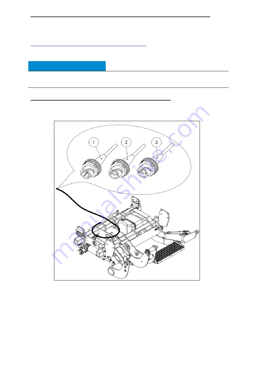
Route the power cable and the cable for the cabin switch unit to the junction box
provided (Fig. 18).
Legen
d:
Item 1
Connector for cabin switch unit
Part No. 20 910 754
Item 2
Connector for positive cable (red)
Part No. 20 907 673
Item 3
Connector for negative cable (blue)
Part No. 20 907 673
Fig. 18
Summary of Contents for GPC X1-LDF
Page 1: ...GPC X1 LDF liftgate Installation Manual for Mercedes Benz Sprinter...
Page 11: ...Introduction 5 2 1 4 Accessories kit Fig 4...
Page 13: ...Introduction 7 2 1 5 Installation adapter kit 22 911 216 Fig 5...
Page 71: ...Useful information 65 8 2 Assembly drawings of installation adapters...
Page 72: ...Useful information 66 8 3 Electrical circuit diagram...
Page 73: ...Useful information 67 8 4 Hydraulic circuit diagram...


