


Copyright 2015 by Maxford USA
Page
9
RUMPLER TAUBE / Doc. Nbr. S160113
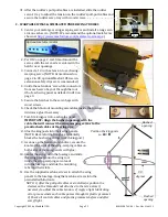
15.
Install your tail-warping servo in the supplied servo tray.
16.
Glue the servo tray into
the fuselage as shown
at the right.
17.
Center the tail-warp-
ing servo.
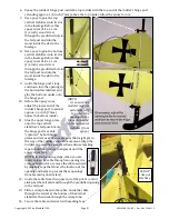
18.
Select a long servo arm
and install an EZ-Link
connector at the arm’s
outer hole as shown at
the right. (NOTE: A
conservative modeler
may use an optional
metal servo arm with
one side removed as the
tail-warping servo arm.
You may learn about optional metal servo arms at
http://www.maxfordusa.com/metalservoarm.aspx
.)
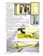
19.
Attach the elevator pushrod’s pre-formed Z-bend to a control horn at
the front side of the pilot’s control stick.
20.
As shown above, position the pilot’s control stick approx. 2
3/4
-inches
(70 mm) behind the rear cockpit’s front former and snug the EZ-Link
connector onto the pushrod.
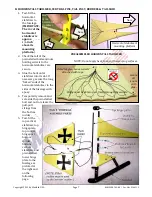
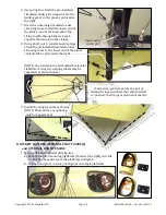
21.
Remove the masking tape from the cable at the bottom vertical
stabilizer’s tail post. Draw the cable snug and allow the string to slide
through the swivels to self-adjust lengths and equalize tension on each
segment of string.
22.
Secure the cable with the crimp
tube and trim off the loose end of
cable.
23.
Attach an approx. 26-inch (66 cm)
long cable to a threaded metal
rod with a crimp tube. Twist a
clevis half way onto the rod.
Attach the clevis to the horn at
the lower end of the pilot’s
control stick.
24.
Pull the cable through the
fuselage with coat-hanger wire
as pictured below.
Samples of typical
long servo arms.
Tail
Nose
Approx. 2
3/4
-inch
(70 mm)