Maxford USA RUMPLER TAUBE Instruction Manual Download Page 5

Copyright 2015 by Maxford USA


Page 

5


RUMPLER TAUBE  /  Doc. Nbr. S160113


3.


Returned merchandise that is accepted by Maxford USA for credit is subject to a 10% to 20% 

restocking fee (the final amount will be determined by Maxford USA upon receipt and examination of 

the returned merchandise). 
Return address:  

Maxford USA 


15939 Illinois Avenue, #B-C 

(

Print the RMA# issued by Maxford USA


Paramount, CA  90723  


on your package


near our address.

)


IV.  SPECIFICATIONS                                     

(NOTE: All dimensions and weights are approximate.)


Wingspan  .........................................................................................................................................................   64 inches 


Length  ................................................................................................................................................................   47 inches 


Wing area  .......................................................................................................................................   653 square inches 


Radio  .......   Minimum of 5 channels with 2 metal gear servos, 1 standard servo and 1 micro servo 

(If a glow engine is used, a 2

nd

 micro servo is needed) 


Flying weight   ...........................................   Around 5 pounds (depending on power and radio systems) 


Minimum power ................................................................................................................   400W brushless motor 


Propeller   ........................................   11x7 to 12x6 or as recommended by your power system’s maker 

V.  SPECIAL FEATURES 


Unique balsa, plywood and composite semi-scale model of this historic pre-World War I aircraft. 


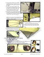
Fully functional wing warping and horizontal-tail warping. Most control cables are pre-rigged. 


Functional pilot’s control stick. 


Shock absorbing main gear and spring-loaded articulated tail skid. 


Adjustable-depth motor-mounting box, able to accept a wide range of power system options. 


Separate front and rear cockpit hatches, secured with strong permanent magnets. 


This ARF comes with two cowls: 1 precut to fit the optional dummy engine for an electric power 
setup, plus a second cowl that has not been precut, suitable for use with a glow-engine. 


An optional glow-engine firewall, replacement parts and optional detail-upgrade items are available. 

VI.  PARTS LIST 

1.


Included items 


Prebuilt and precovered airframe. 


Preassembled control-rigging for wing- 
and horizontal tail-warping. 


Composite wing-warping kingposts. 


Twin cockpits. 


Adjustable motor mounting box.


Preassembled functional pilot’s 

control stick assembly.


Preassebled landing gear assembly. 


All required hardware.


Scale stick-on markings. 


Standard main wheels and tail skid.


2.


Items you must supply to complete this ARF 


Epoxy and cyanoacrylate (CA) adhesives and threadlock 
compound. 


Common household shop tools (screwdriver, pliers, etc.). 


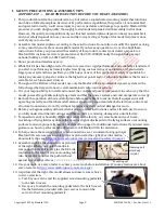
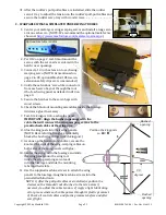
Outer rotor motor and electronic speed control (ESC) such as the 

Maxford USA Uranus 35425 motor (shown at the right) and 
Uranus 60A ESC with a 3S or 4S approx. 2,200 mAh LiPo battery, 

or as recommended by your vendor, or a 40-class glow engine, 

throttle pushrod and fuel tank. 


A five or more channel radio with two high-torque metal gear  

servos (such as a Hitec HS-645MG) for wing warping/roll control, two 12-inch servo extensions, a 
standard servo (such as a Hitec HS-311) for tail warping/pitch control and a micro servo (such as a 

Hitec HS-55 or E-Max ES08A) for the rudder. If a glow engine is used, a 2

nd

 micro servo is needed to 

operate the throttle. 


An 11- to 12-inch diameter by 6- or 7-inch pitch propeller (depending on your flying style) or as 

specified for your electric power system. 
 

Summary of Contents for RUMPLER TAUBE

Page 1: ...uraging us to develop and introduce this semi scale model of a Rumpler factory produced Taube This is the first and only radio controlled ARF model with functional wing and tail warping Built to about...

Page 2: ...ty to install and connect the control and power components in such a way that the model passes all applicable safety range tests and that the power system and controls operate correctly 7 Recheck the...

Page 3: ...pictured at the right 19 If Mylar covering material hides a CA hinge s slot find and open the slot by care fully pressing with a fingernail or sharp hobby knife 20 To obtain good wood to wood gluing...

Page 4: ...yment of this hobby III LIMITED WARRANTY LIABILITY WAIVER RETURN POLICY Maxford USA guarantees this kit to be free from defects in material and workmanship at the time of purchase Our products have be...

Page 5: ...owls 1 precut to fit the optional dummy engine for an electric power setup plus a second cowl that has not been precut suitable for use with a glow engine An optional glow engine firewall replacement...

Page 6: ...gine setup VII ASSEMBLY INSTRUCTIONS A SIMULATED RADIATORS PILOT S CONTROL STICK 1 Attach a simulated radiator to each side of the fuselage 2 Select option 1 or option 2 described below to attach an a...

Page 7: ...zer to the sides of the fuselage with epoxy 4 Temporarily remove and set aside the preinstalled bolt and nut to release the pull pull strings from the bottom rudder 5 Test fit the top vertical stabili...

Page 8: ...inch 7 mm below the bottom rudder 11 Glue the upper hinge plate onto the top vertical stabilizer s tail post Ensure the hinge post is evenly captured by both hinge plates and remove any excess epoxy t...

Page 9: ...ot s control stick 20 As shown above position the pilot s control stick approx 2 3 4 inches 70 mm behind the rear cockpit s front former and snug the EZ Link connector onto the pushrod 21 Remove the m...

Page 10: ...e the cable attached to the pilot s control stick along either side of the rudder servo 29 As pictured at the right reattach the rudder s control strings to the lower rudder and apply epoxy to lock al...

Page 11: ...ue if necessary 7 Test fit a kingpost into each wing panel IMPORTANT Align the bushed openings with the cable that will connect the wing warping servos to the preattached cables at the wing tips 8 Glu...

Page 12: ...the predrilled holes on the bottom of the wing panels 14 Glue the trusses onto the truss supports Use clevises to adjust cable tension NOTE DO NOT GLUE either truss to the fuselage if you want to rem...

Page 13: ...ottle channel on your receiver 3 With no propeller on the motor run your motor slowly and only for the few seconds necessary to observe its direction of rotation If the motor rotates in the wrong dire...

Page 14: ...stick the Iron Cross markings to the tops of the wing panels and to both sides of the twin rudders as pictured below 2 Locate the 3 pieces of the top side wing wire attachment structure pictured at th...

Page 15: ...f the pilot s control stick as pictured at the right NOTE Any twisted pair of simulated horizontal stabilizer or wing tip warping cables may be separated as shown below 9 Install the wing tip wires as...

Page 16: ...l Deflection PITCH 3 4 inches 2 cm from neutral at the trailing edge of the horizontal stabilizer YAW 2 3 4 inch 7 cm left and right from center at the trailing edge of either rudder ROLL 1 inch 2 5 c...

Page 17: ...entirely at your own risk PLEASE ENJOY YOUR HOBBY AND FLY SAFELY Manufactured by Maxford USA RC Model Mfg Inc Distributed by Maxford USA RC Model Distribution Inc Telephone voice 562 529 3988 15939 I...

Reviews: