


Copyright 2015 by Maxford USA
Page
11
RUMPLER TAUBE / Doc. Nbr. S160113
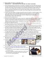
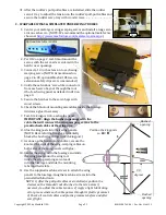
31.
After the rudder’s pull-pull cables are installed, slide the rudder
servo’s tray to adjust the tension on the rudder’s pull-pull cables and
secure the rudder servo tray with wood screws.
C.
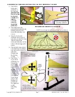
WARPABLE WINGS & SIMULATED UNDER-WING TRUSSES
1.
Center your metal gear wing-warping servos and install a long servo
arm on each servo. (NOTE: We recommend the optional metal arms
shown at
http://www.maxfordusa.com/metalservoarm.aspx
2.
Per #12 on page 2, test-fit and mount the
servos with the servo arms centered in the
hatch cover openings.
3.
Connect a 12-inch extension to each wing-
warping servo. (NOTE: As mentioned on
page 2 in #9, optional Maxford USA servo-
extension safety clips are recommended.)
4.
Guide the extensions’ servo-like connectors
from each servo bay out through the root
rib of each wing panel as detailed in #13 on
page 3.
5.
Secure the hatches to the servo bays with
wood screws.
6.
Check the blind-nut mounting assemblies inside the fuselage.
Add more glue if necessary.
7.
Test-fit a kingpost into each wing panel.
IMPORTANT: Align the bushed openings with the
cable that will connect the wing-warping servos to the
preattached cables at the wing tips.
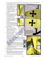
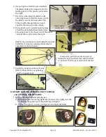
8.
Glue the kingposts into their wing panels.
(NOTE: Be careful that no glue accidentally
blocks the bushed openings in each kingpost.)
9.
As done on the horizontal stabilizer, secure the
knots at the ends of the wing-warping cables on
both sides of the wing panels with glue.
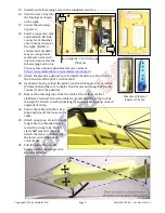
10.
Center the wing rod in the fuselage and slide
the wing panels onto the wing rod.
Guide the wing-warping servo leads
into the fuselage and slide the mounting
tabs into their slots.
11.
Use the supplied machine screws to attach the wing
panels to the fuselage. Snug the machine screws into the
preinstalled blind nuts.
NOTE: 1) After the pull-pull cables are installed, reposition the
clevises on the threaded rods attached to the servo arms if
necessary to adjust the cable tension. 2) Apply a light lubricating
oil or grease where each cable passes through its plastic grommet.
3) Check all control cables and plastic grommets before and after
every flight.
Bushed
opening
Bushed
opening
Position the kingposts
so
A = B
Optional metal servo arm
Nose
90
degrees