


Copyright 2015 by Maxford USA
Page
7
RUMPLER TAUBE / Doc. Nbr. S160113
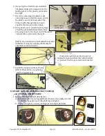
B.
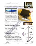
HORIZONTAL STABILIZER, VERTICAL FINS, TAIL POST, RUDDERS & TAIL SKID
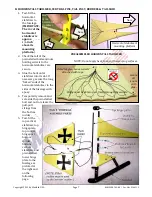
1.
Test-fit the
horizontal
stabilizer to
the fuselage.
(
IMPORTANT:
The
TOP
of the
horizontal
stabilizer is
approx.
1/2
-inch
above its
mounting
platform
.)
2.
Check that all of the
preinstalled bolts and nuts
holding swivels to the
horizontal stabilizer are
secure.
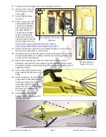
3.
Glue the horizontal
stabilizer into its slot. If
necessary, secure the long
‘forked’ ends of the
horizontal stabilizer to the
sides of the fuselage with
epoxy.
4.
Temporarily remove and
set aside the preinstalled
bolt and nut to release the
pull-pull
strings from
the bottom
rudder.
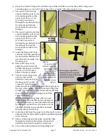
5.
Test-fit the
top vertical
stabilizer, top
hinge plate,
top rudder,
hinge post,
bottom
rudder,
bottom
vertical
stabilizer, and
preinstalled
lower hinge
plate to the
fuselage as
pictured at
the right and
on the
following
page.
Tail
Nose
Horizontal stabilizer’s
mounting platform
Nose
TOP
of the
horizontal
stabilizer
PREASSEMBLED HORIZONTAL STABILIZER
NO HEAT
Avoid tangles: Leave swivels
attached with tape.
Secure
all
knots
with
glue.
String must be able to pass freely through the swivels.
NOTE: Do not apply heat to any of the warping surfaces.