


Copyright 2015 by Maxford USA
Page
10
RUMPLER TAUBE / Doc. Nbr. S160113
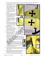
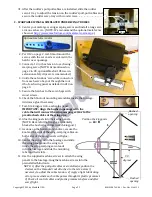
25.
As shown at the right,
setup the horizontal
stabilizer’s top pull-
pull cable the same as
the bottom pull-pull
cable. Secure the
cable with a crimp
tube and trim off the
loose end of cable.
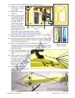
26.
Install your rudder
servo in the provided
servo tray as shown
below.
27.
Attach two(2) approx.
22-inch (56 cm) long
cables to the outer
openings of the
longest arm provided
with your servo that
will fit inside the
fuselage as pictured
at the right.
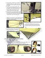
28.
Center the rudder servo and position it toward
the rear of the slotted opening behind the pilot’s
control stick. (NOTE: Guide the cable attached to
the pilot’s control stick along either side of the
rudder servo.)
29.
As pictured at the right, reattach the rudder’s
control strings to the lower rudder and apply epoxy to lock all four
swivels at the same angle.
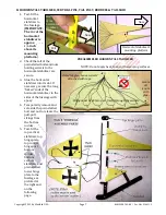
30.
Install the rudder’s pull-pull cables as pictured below.
Point
the
swivels
toward
the horizontal
stabilizer and
secure with
epoxy.
Crimp tubes
Crimp
tube
Crimp
tube
Tail
NOTE: 1) After the pull-pull cables are
installed, reposition the clevis on its threaded
rod attached to the lower end of the control
stick if necessary to adjust the cable tension.
2) Apply a light lubricating oil or grease where each
cable passes through its plastic grommet. 3) Check all
control cables and plastic grommets before
and after every flight.
NOTE: Do not remove cable and tape
until you are ready
to install a cable.