


Copyright 2015 by Maxford USA
Page
16
RUMPLER TAUBE / Doc. Nbr. S160113
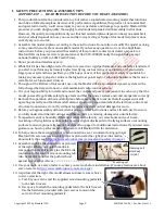
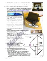
2.
If you will install an
optional scale Mercedes
dummy engine:
a.
Test-fit the dummy
engine into the opening
at the top of the cowl
with the engine’s
exhaust pipes at the
right as viewed from
the pilot’s seat.
b.
Attach the engine to the
top of the motor mount-
ing box with two1 cm
(
3/8
-inch) wood screws.
(NOTE: Using an
optional dummy
engine with a glow engine is not recommended.)
Congratulations! Assembly is fi nished!
VIII. SETUP & ADJUSTMENTS
Even though this ARF may be capable of more aerobatic performance, we recommend that it looks
best when flown in a scale-like manner, like the original Rumpler Taube, with flat, gentle turns.
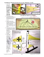
1.
Center of gravity (CG):
For your initial flight we
recommend your Rumpler
Taube should balance
between approx. 3
1/4
-
and 4
1/4-
inches (8.3 to
10.8 cm) behind the
leading edge of the wing
as pictured at the right.
(NOTE: Extra nose weight
will be needed if using a
3S Lipo battery.)
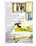
2.
Initial deflections:
Channel
Recommended Initial Deflection
PITCH .... +
3/4
-inches (+2 cm) from neutral at the trailing edge of the horizontal stabilizer.
YAW ....... 2
3/4
-inch (7 cm) left and right from center at the trailing edge of either rudder.
ROLL ...... +1-inch (+2.5 cm) from neutral at the trailing edge of each wing tip.
NOTE: 1) If you employ a wing-warping to rudder mix, we recommend starting with a max. of
approx. 25%. 2) Internal structures and/or control linkages may become worn or damaged by
attempting to excessively bend the horizontal stabilizer or the wing tips.
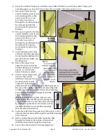
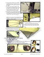
3.
An airplane this size may not need to have its wing removed for transportation or storage.
To remove the wing:
a.
Disconnect the springs that connect the wing-wires to the center brace, the lower end of the
pilot’s stick and the landing gear’s cotter pins. Remove the screws that secure the wings to the
fuselage and attach the landing gear to the wing. Disconnect the wing’s servo extensions from
the receiver. Slide the wing panels away from the fuselage.
b.
Reverse the procedure to reattach the wing panels and landing gear.
NOTE: Please check our Website at
additional photos, videos and other helpful information.
NOTE: This brace is approx. 4
1/4
-inches behind the leading edge.