TROUBLESHOOTING
10 - 14
D-MAXE with OI-B/OI-N
www.maxcessintl.com
MI 2-296 1 D
Fuse replacement
The printed circuit boards in the D-MAXE controller and the
operator interface are static sensitive devices. All standard ESD
precautions must be followed when touching or handling the
printed circuit boards.
These fuses should be replaced by qualified personnel only.
Follow the instructions shown below for fuse replacement.
A common cause for blown fuses is an incorrect power supply
connection - especially reversed polarity. Before applying power
after replacing fuses, verify correct power supply wiring per
If the units will not power on after fuses are replaced and correct
power supply connections have been verified, the units must be
returned to Maxcess for repair.
Controller fuses
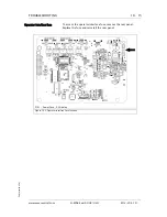
1. To access the controller fuses, remove the screws (A) that
secure the power end cover assembly to the enclosure.
Carefully remove the assembly.
2. Replace the necessary fuse(s).
3. Ensure that all connectors are engaged properly.
4. Re-install the end cover assembly and tighten the screws.
F4001 - Control power, 6.3A delay
F4002 - Drive power,10A delay
Figure 10.1: D-MAXE controller fuse locations
F4001
F4002
(A) 4x
(A) 6x
F4001
F4002
D-MAXE 2
D-MAXE 3


