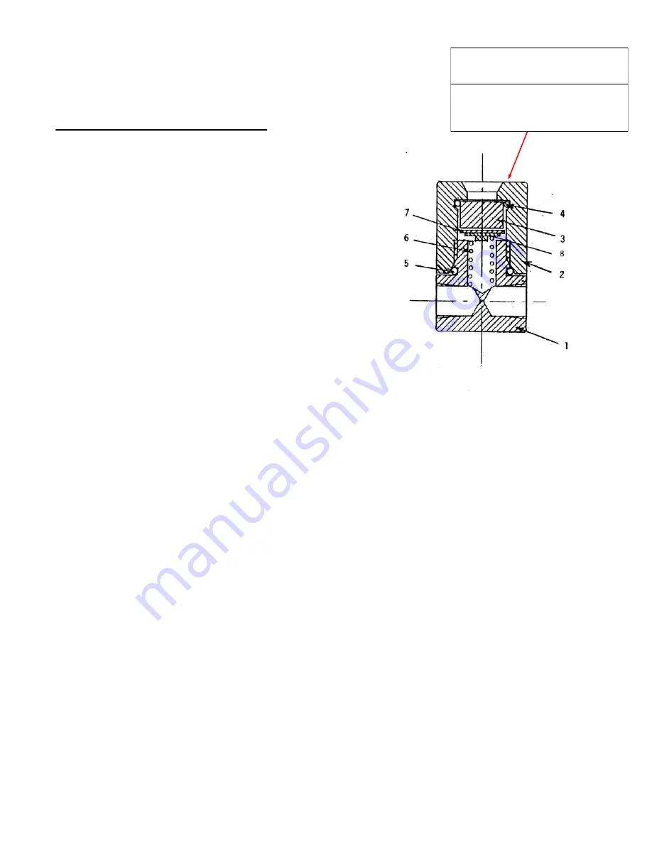
Assembly and Disassembly
Model MI
-
4000 Visual Indicator
Unscrew by hand , counter
-
clockwise,
to remove and replace elements.
Reinstall cap hand tight.
BLEED ALL PRESSURE FROM
UNIT AND SHUT OFF POWER
Item
Qty
Part No.
Description
1
1
583
Body
2.
1
584
Cap
3
1
593
Window
4
1
592
-
1
O ring 2
-
018
5
1
592
-
2
O ring 2
-
019
6
1
592
-
3
Spring
7
1
592
-
5
Indicator humidity (blue)
8
1
592
-
6
Indicator CO (beige)
NOTES:
1.
Technical bulletin – 588
2.
Use Dow silicone grease 111 or equivalent on
seals and threads
3.
Tighten cap hand tight only
4.
Install window (3) with smooth, small diameter
against O ring (4)
5.
Insure window (3) is fully against should
er
of cap (2)
6.
Avoid spring or other hard objects touch
ing
window
7.
Install so both elements can be seen through window,
insure spring is in place to hold element against
window
8.
When installing humidity element place it in cap (2)
with blue face against window
9.
COLOR CHANGE:
-
Blue to pink means high humidity
-
Beige to dark brown means dangerous levels of
carbon monoxide
NOTE:
1.
DO NO TOUCH ELEMENTS WITH HANDS
USE CLEAN TWEEZERS OR CLEAN NEEDLE
NOSE PLIERS
2.
MAKE SURE COMPRESSOR AND FILTER
HOUSING ARE COMPLETELY DRAINED OF
ALL AIR PRESSURE PRIOR TO ATTEMPTING
REMOVAL OF CAP FOR MAINTENANCE
.
Page 19 of 22


