background image

Digital Video Recorder 


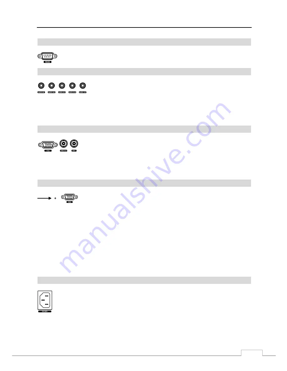
RS232C Port 


Audio In/Out 


NOTE:  It is the user’s responsibility to determine if local laws and regulations permit recording audio. 
 

The DVR does not have amplified audio output, so you will need a speaker with an amplifier.  The DVR 
does not have a pre-amplifier for audio input, so the audio input should be from an amplified source, 
not directly from a microphone. 


Video Out 


NOTE: The 

VGA 

and 

Video Out (BNC) connectors may be connected to individual monitors for simultaneous 

operation. 


Factory Reset Switch 


The DVR has a 

Factory Reset

 switch to the left of the VGA connector on the rear panel.  

This switch will only be used on the rare occasions that you want to return all the settings 
to the original factory settings.


CAUTION:  When using the Factory Reset, you will lose any settings you have saved. 


To reset the unit, you will need a straightened paperclip: 

1.  Turn the DVR off. 
2.  Turn it on again. 
3.  While the DVR is initializing, the front panel LEDs will blink.  When the front panel LEDs blink, poke the 

straightened paperclip to the unlabeled hole in the left of the VGA connector. 

4.  Hold the switch until all the LEDs on the front panel are lit. 


NOTE:  When the DVR successfully resets to factory defaults all the LEDs on the front panel flash five times. 


5.  Release the reset switch.  All of the DVR’s settings are now at the original settings it had when it left the factory. 


Power Cord Connector 


An RS232 port is provided to connect a remote control keyboard. 


Your DVR can record audio from up to four sources.  Connect the audio sources to 

Audio In 1

Audio In 2

Audio In 3

 and 

Audio In 4

 as needed using RCA jacks.  

Connect 

Audio Out

 to your amplifier. 


A VGA connector is provided so that you can use a standard, multi-sync computer monitor 
as your main monitor.  Use the cable supplied with your monitor to connect it to the DVR. 


Connect the main monitor to the 

Video Out

 connector.  Connect the spot monitor to the 

SPOT

 connector as needed. 


Connect the AC power cord to the DVR and then to a wall outlet. 

Summary of Contents for DRC816H

Page 1: ......

Page 2: ......

Page 3: ...PROVIDE REASONABLE PROTECTION AGAINST HARMFUL INTERFERENCE WHEN THE EQUIPMENT IS OPERATED IN A COMMERCIAL ENVIRONMENT THIS EQUIPMENT GENERATES USES AND CAN RADIATE RADIO FREQUENCY ENERGY AND IF NOT IN...

Page 4: ...chnician to restore the equipment to its normal operation E If the equipment has been dropped or the cabinet damaged F When the equipment exhibits a distinct change in performance this indicates a nee...

Page 5: ...Chapter 3 Configuration 7 Front Panel Controls 7 Camera Buttons 1 to 16 8 Power LED 8 HDD LED 8 Alarm Out LED 8 Network LED 8 Clip Copy LED 9 PANIC Button 9 ALARM Button 9 CLIP COPY Button 9 ZOOM PTZ...

Page 6: ...toring 41 Live Monitoring Menu 42 Active Cameo Mode 43 Zoom Mode 43 PTZ Mode 43 Event Monitoring 45 Covert Camera 45 Spot Monitoring 45 Using a Mouse 45 Recording Video 47 Panic Recording 47 Recording...

Page 7: ...reen 15 Figure 14 Storage Status screen 16 Figure 15 User setup screen 16 Figure 16 Setup wizard screen 17 Figure 17 Quick Setup wizard screen 18 Figure 18 Network Setup wizard screen 19 Figure 19 Shu...

Page 8: ...eo Loss Settings screen 38 Figure 52 Video Loss Actions 1 screen 38 Figure 53 Video Loss Actions 2 screen 38 Figure 54 Health Check screen 39 Figure 55 Storage screen 39 Figure 56 System Event Actions...

Page 9: ...R T protocol Technical Overview In addition to replacing both a time lapse VCR and a multiplexer in a security installation your DVR has many features that make it much more powerful and easier to use...

Page 10: ...he 8 and 16 channel digital video recorders The DVRs are identical except for the number of cameras and alarms that can be connected and the number of cameras that can be displayed For simplicity the...

Page 11: ...required to install the DVR Refer to the installation manuals for the other items that make up part of your system Figure 2 16 Channel DVR rear panel Video Input Video Loop Through RS485 Port Alarm I...

Page 12: ...such as buzzers or lights Connect the device to the C Common and NC Normally Closed or C and NO Normally Open connectors NC NO is a relay output which sinks 2A 125VAC and 1A 30VDC See Chapter 3 Config...

Page 13: ...on again 3 While the DVR is initializing the front panel LEDs will blink When the front panel LEDs blink poke the straightened paperclip to the unlabeled hole in the left of the VGA connector 4 Hold t...

Page 14: ...FURNITURE DO NOT INSTALL POWER CORDS UNDER RUGS OR CARPET THE POWER CORD HAS A GROUNDING PIN IF YOUR POWER OUTLET DOES NOT HAVE A GROUNDING PIN RECEPTACLE DO NOT MODIFY THE PLUG DO NOT OVERLOAD THE CI...

Page 15: ...of the buttons have multiple functions The buttons on the infrared remote control while laid out differently perform the same functions as those on the front panel The following describes each button...

Page 16: ...he button 1 zooms in the screen and the button 2 zooms out the screen pressing the button 3 focuses near and button 4 focuses far and pressing the button 5 moves to the preset and button 6 saves the p...

Page 17: ...he DISPLAY SPOT button toggles between different display formats The available formats are PIP 2x2 1 5 1 7 3x3 and 4x4 Pressing and holding the button for three seconds or longer allows you to select...

Page 18: ...on moves to the next image and pressing the button moves to the previous image PLAY PAUSE Button In the live monitoring mode pressing the button freezes the current screen and the screen displays icon...

Page 19: ...r the setup screens The Login screen appears Select a User and enter the password by pressing the appropriate combination of Camera number buttons and then the button There is no default password when...

Page 20: ...ed your title highlight OK and press the button Highlight the box beside System ID and press the button Change the number by highlighting it and using the Up and Down arrow buttons to increase and dec...

Page 21: ...settings the time related settings Date Time Time Zone and Daylight Saving Time will NOT be changed CAUTION The USB device must be FAT16 or FAT32 format Highlight Show System Log and press the button...

Page 22: ...pressing the Left and Right buttons or scrolling the mouse wheel up and down Highlight Use Daylight Saving Time and press the button Pressing the button toggles between On and Off Highlight the Holid...

Page 23: ...be able to format the device for recording When selecting Not Using from Use As and highlighting the Format button the device will not be used for recording You can also set aside space to store temp...

Page 24: ...item is a Group Name If there is a in front of the Group Name it indicates that the group has been expanded and all of the User Names within that group are displayed below the Group Name If there is a...

Page 25: ...mode on a local system or a PC running RAS System Check The user can view the remote system status or check the remote system status as a batch process on a PC running RAS Record Setup The user can es...

Page 26: ...k the Next button Record Method Setup Select the desired recording mode from Motion Event Record Continuous Motion Event Record Continuous Record NOTE You should understand each recording mode before...

Page 27: ...Standard 3 ips Time High 5 ips Event Continuous Record Very High 30 ips High 5 ips Standard 3 ips Record Video Quality HVQPP High Video Quality Priority Profile SRP Standard Recording Profile LRTPP L...

Page 28: ...ct the box to use the DVR Name Service DVRNS Server Enter the IP address or domain name of the DVRNS server Port Set the port number of the DVRNS server Use NAT Select the box to use the NAT Network A...

Page 29: ...ion settings require higher Transfer Speed settings The transfer speed you set is the maximum speed Depending on the network environment this speed may not be achieved You can limit the network bandwi...

Page 30: ...ul when accessing a port on a private IP address NOTE For the UPnP service to work the NAT device should support the UPnP Port Forwarding function and the function should be set to enabled You cannot...

Page 31: ...to toggle between On and Off NOTE The DVRNS DVR Name Service allows the DVR to use Dynamic IP addresses for remote connection When this feature is On you can access your DVR remotely using the DVR na...

Page 32: ...ess the button Set the end port number of the RTP server obtained from your system administrator Highlight Use Mobile and press the button to toggle between On and Off When set to on you can access a...

Page 33: ...ys Figure 27 Notification Mail setup screen The Mail account can be turned On or Off by highlighting the boxes under the No heading and pressing the button Highlight the and press the button to add a...

Page 34: ...t the box beside Sender and enter the sender s e mail address Use the virtual keyboard to enter the e mail address NOTE The e mail address must include the character to be a valid address Highlight th...

Page 35: ...d pressing the button Change the number by highlighting it and using the Up and Down arrow buttons to increase and decrease the number The PTZ ID number can be set from 0 to 256 Highlight the Setup bo...

Page 36: ...hedule Highlighting the boxes under the Column heading and pressing the button allows you to edit the information in those boxes The Day box allows you to select the days that the alarm schedule will...

Page 37: ...screen You can adjust the transparency of the setup screens by highlighting Transparency and using the Left and Right arrow buttons Highlighting OSD Margin and pressing the button displays how OSD tex...

Page 38: ...tton Figure 36 Spot Monitor screen Highlight the VGA tab to switch to the VGA screen Highlight the box beside Resolution and press the button You can select from 800x600 1024x768 and 1280x1024 Highlig...

Page 39: ...e space has been used When Recycle is turned off the DVR stops recording once all available storage space has been used Highlight the Event Record Dwell box and set the length of time you would like t...

Page 40: ...e disk is installed in the unit the DVR records video on the disks sequentially based on time And these sequentially recorded videos have the advantage that you can search recorded video easily even t...

Page 41: ...corner of the screen during the scheduled times When the DVR is in the Event mode the red icon displays at the top left corner of the screen The DVR will record and displays the icon at the top left...

Page 42: ...in the Time or Time Event mode it ignores the pre event settings and follows the time settings Event Setup Figure 44 Event menu Alarm In Highlight Alarm In in the Event menu and press the button The A...

Page 43: ...edule tab Highlight the desired box under the Notify heading and press the button The Alarm In Notify menu appears You can toggle the entire list On and Off by highlighting Notification and pressing t...

Page 44: ...tivates inactive highlighted blocks and deactivates active highlighted blocks Select All Activates all blocks to detect motion Clear All Deactivates all blocks so that they will not detect motion Reve...

Page 45: ...motion on the selected camera s input it triggers output signals on all the associated Alarm Out connectors You can also have the DVR s internal buzzer sound if motion is detected on the selected cam...

Page 46: ...n the Record Schedule setup screen Highlight the box under the Alarm Out heading and press the button A list of Alarm Outputs appears You can associate as many Alarm Outs with that camera as you wish...

Page 47: ...e each alarm in and pressing the button allows you to change the interval that you want the DVR to run self diagnostics on Alarm Inputs You can select from 1 hr to 30 days or Never Highlight the Stora...

Page 48: ...y action to work the DVR should be registered in the RAS Remote Administration System Event Status Highlight Event Status in the Event menu and press the button The Event Status screen appears Figure...

Page 49: ...nfiguration Turning on the Power Once you have installed the DVR following the instructions in Chapter 2 Installation it is ready to record Live Monitoring As soon as the DVR completes its initializat...

Page 50: ...uence for the cameo sequence monitoring should be selected in the Display setup screen Main Monitor tab Camera Menu Selecting Camera Menu in the Live Monitoring menu displays the following Camera Menu...

Page 51: ...meo menu displayed when pressing the CAMEO button also exits the Active Cameo mode The active cameo mode will remains in effect for 15 seconds if there is no further operation In active cameo mode pre...

Page 52: ...Preset menu While in the PTZ mode pressing the MENU button and selecting Advanced PTZ in the menu displaying at the top of the screen displays the Advanced PTZ menu Set the feature you wish to contro...

Page 53: ...een Settings tab that camera appears to be Off unless a user with Covert Camera View authority logs into the system The camera title will be grayed out and status icons will not be displayed on the mo...

Page 54: ...s displayed in the top left and you can select the camera you want to display on the main channel screen Select a channel on the screen and click the right mouse button to display the Camera Menu Sele...

Page 55: ...not in the Recycle mode and all available storage space has been used panic recording will not operate Recording Audio If the DVR was set up to record audio it will record audio from up to four inputs...

Page 56: ...Edit in the cameo menu displayed when pressing the MENU CAMEO button also exits the Active Cameo mode NOTE A cameo is defined as any cell within multi screen display The cameo mode allows you to chan...

Page 57: ...age Go to the Last Selecting Go to the Last displays the last recorded image Go to the Date Time Selecting Go to the Date Time displays the Go to the Date Time screen Move the cursor over the date and...

Page 58: ...cting Exit in the Search menu exits the search mode and enters the live monitoring mode Event Log Search Figure 65 Event Log Search screen The DVR maintains a log of each time the Alarm Input port is...

Page 59: ...ping start and stop time When set to On you will be asked to select one of the overlapping start and stop time When set to Off the DVR will display search results from all start times to all stop time...

Page 60: ...e Expanded view mode switches to the Standard view mode Selecting or located at the bottom zooms the record table Selecting displays eight hours 1 minute based and selecting displays 24 hours 3 minute...

Page 61: ...button The selected date and time will display NOTE It is possible that no recorded image displays on the current screen Press the DISPLAY button and change the screen mode to 4x4 You will be able to...

Page 62: ...at must be activated Setting the Min Blocks will only be available if Motion Search is selected Once you set your desired search conditions highlight Search and press the button to display the search...

Page 63: ...g speed might decrease While copying video clips on the DVD RW the DVR will stop archiving video data until clip copy is finished When the error message Firmware update of the optical drive is require...

Page 64: ...eed to install any special software on your personal computer to review the video clips Refer to RAS manual for instructions on how to review video clips you have copied NOTE During Clip Copy you cann...

Page 65: ...identical to Windows 98 1 Connect the USB hard disk drive to your computer using the USB Cable 2 Turn on your computer The Add New Hardware wizard window will appear 3 Install the device driver for t...

Page 66: ...t is recommended that websites open windows without address or status bars by changing the internet setting Go to the Tools Internet Options Security tab Click the Custom level button Select Enable fo...

Page 67: ...ed in the first cell of the new layout Click the camera button to select the camera to be viewed Click the to adjust the brightness contrast saturation and hue of monitoring image Click the to control...

Page 68: ...era Title blank causes the camera name set up on the remote site to display The icon will display on each camera screen when audio communication is available between the WebGuard system and a DVR Web...

Page 69: ...hat has recorded audio Single Screen Layout Only Aspect Ratio Changes the image aspect ratio Deinterlacing Using a deinterlace filter for interlaced video enhances image display quality by eliminating...

Page 70: ...ock of the first segment to five o clock of the first segment From four o clock of the first segment to five o clock of the second segment From four o clock of the second segment to five o clock of th...

Page 71: ...ings Live Video Very Bright If a cable is attached to the Loop connector make certain it is connected to a properly terminated device DVR has stopped recording If hard disk drive is full you will eith...

Page 72: ...ion error 3 No media 4 Kernel version error 4 Invalid media 100 Upgrade device mounting failed 5 File already existed 101 Package is not found 6 Not enough space 102 Extracting package failed 7 Creati...

Page 73: ...DC Alarm Output 2 relay output programmable as NC or NO 2A 125VAC 1A 30VDC Alarm Reset Input 1 TTL terminal block Internal Buzzer 80dB at 10cm Network Connectivity 10 100 Mbps Ethernet RJ 45 Audio Inp...

Page 74: ...Temperature 41 F to 104 F 5 C to 40 C Operating Humidity 0 to 90 Power 100 to 240 VAC 1 2 0 6 A 60 50Hz Power Consumption Max 45W Approvals FCC UL CB CE CAUTION Risk of Explosion if Battery is replace...

Reviews: