background image


Matan JetSet 3.2P Printer 

29 

User Manual 


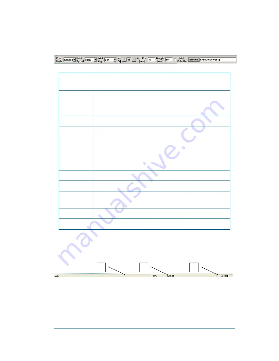
Print settings bar:

 Set frequently used settings such as: print speed, print mode, ink 

quantity, and material’s margin. 


Operation of Toolbar:

 Click the Open File button to add files to the printing jobs list. Select the 

file to be printed, and click the Start Print button to start the operation. 

Print Mode: 

Select the print mode 

There are six modes: Three Pass, Draft, Normal, Enhanced, Master and 

Ultra. 

Print Speed: 

Define the print speed 

Print Align: 

The printing position of the image on the material 

Left: left side align 

Right: right side align 

Center: middle position align 

Align mode is only used for edge checking. 

Ink: 

Ink density adjustment 

Zero Pos: 

Distance between the cleaning device and the right limited switch 

Margin: 

Define the blank margin (refers to the distance between the left edge of 

material the starting position of printing) 

Print Color Bar: 

Enable Print Color Bar use in printing 

Browse: 

Add all RIP files under specified directory to the printing jobs list 


Status bar: 

Shows the printing progress bar [1], and the absolute position of the 

print carriage [2].


2

Summary of Contents for JetSet 3.2P

Page 1: ...User Manual...

Page 2: ...ARTING YOUR PRINTER 16 2 3 INK FILLING PROCEDURE 18 2 4 PRINTING CONTROL PROCESS 18 2 5 REMOVING MATERIAL 18 2 6 SHUTTING DOWN 18 CHAPTER 3 USE OF CONTROL SOFTWARE 19 3 1 OBJECTIVES 19 3 2 FUNCTIONS 1...

Page 3: ...41 3 4 6 6 Region Printing for Large Images 41 3 4 6 7 Multi file Printing 42 3 4 6 8 Web Printing 43 3 4 6 9 Restore Printing 43 3 4 6 10 RIP EDIT 44 3 5 ERROR AND WARNING CODES 48 CHAPTER 4 OFFSET...

Page 4: ...PRINT HEAD 59 5 2 1 Installation of Print Head 59 5 2 2 Disassembling Print Head 59 5 2 3 Basic Maintenance Knowledge of Print Head 60 5 2 4 How to Fill the Print Head with Ink 60 5 2 5 Cleaning Prin...

Page 5: ...e print heads The automatic cleaning system thus ensures high efficiency safety and convenience The automatic cleaning system is liquid protected The feeding system employs tension control on the mate...

Page 6: ...1 69m H 4 35 5 05m W 0 83m D Weight 942 1200 KG Feeding system Roll to roll with tension control Heating system Pre heating post heating cooling fan and carriage heating Ink supply system Auto continu...

Page 7: ...0 100M Ethernet The above configuration may change in future upgrades Operating system Windows XP Environment requirements Power range 230V AC 10V 50HZ 15A 23A Maximum power 3 5 5 3KW Operating temper...

Page 8: ...Matan JetSet 3 2P Printer 4 User Manual 1 4 Introduction to Main Components Appearance Left up side view 2 5 6 7 8 9 10 11 12 13 14 15 16 17 18 19...

Page 9: ...onitor 2 Left box body Left emergency stop Vacuum adjust 5 Front top 6 Right front door 7 Secondary drying 8 Right box body 9 Cooling fans 10 Left box body 11 Pre heating temperature controller 12 Dry...

Page 10: ...n power SW 27 X axis SW 28 Y axis SW 29 Tension SW 30 Heating SW 31 Contactor 32 Relay 33 Pre heating relay 34 Drying relay 35 Capacitor s 36 Relay 37 Tension adjustor 38 Secondary drying relay 39 Lin...

Page 11: ...Matan JetSet 3 2P Printer 7 User Manual Platform Carriage cleaning position 46 47 43 42 41 44 40 45...

Page 12: ...Printer 8 User Manual Carriage cleaning position 40 Line railway 41 Cable chain 42 Timing Belt 43 Printing platform 44 Lighting 45 Encoder Strip 46 Cleaning system 47 Carriage 48 Cleaning pump 49 Was...

Page 13: ...Matan JetSet 3 2P Printer 9 User Manual Carriage Carriage front Carriage back 51 50 54 52 53 56 55 57...

Page 14: ...rinter 10 User Manual 50 Carriage PCB 51 Secondary ink tank 52 Print head 53 Carriage heating 54 Vacuum display 55 Vacuum controller 56 Ink connect PCB 57 I O card 58 Ink card PCB 59 Cleaning PCB 60 6...

Page 15: ...Matan JetSet 3 2P Printer 11 User Manual The right electric box 67 68 69 72 70 71 73 74 75 76 77 78 79 66...

Page 16: ...lder 66 Linear encoder 67 Cable terminal strip 68 PC power 69 Relay SSR 70 Filter 71 AC24 transformer 72 X Axis servo controller 73 Y Axis servo controller 74 40V Power supply 75 24V Power supply 76 1...

Page 17: ...inter Please see Appendix 3 Warning sign table 1 Battery base 2 Battery connector CON1 3 Monitor 4 Button MODE 5 Button UP 6 Botton DOWN 7 Botton SET 8 I O signal connector CN1A 9 I O signal connector...

Page 18: ...ding roller rack The material should be placed as centrally as possible 3 Pull the material out from in front of the pinch roller toward the back 4 Put the material around the main roller spread the p...

Page 19: ...The rest of the printing process is the same as normal printing To print double face perform the following steps 1 Choose the right material 2 Install the material and mark its installation position t...

Page 20: ...ield to change the front back picture position 6 Repeat adjustments until the printing position is right 2 2 Starting your Printer 1 Insert the printer s main power plug into the power outlet 2 Pull t...

Page 21: ...Printer 17 User Manual 4 Press down the start button and the PC power button After the PC has started open the HV power SW 5 Turn on the tension SW the vacuum adjustor cooling fan SW the AUX dryer an...

Page 22: ...rocess do not open the platform cover or the cleaning position cover do not turn off the HV power SW main power supply or the X Y axis SW otherwise the print process will be terminated 2 During the pr...

Page 23: ...Ultra Freely set enable or disenable for each color Provide three levels of print speed and five levels of feed speed The whole printing process can be configured dynamically Various print solutions i...

Page 24: ...dware Installation and Initialization Insert the image card into the PCI slot of your PC Install driver and application programs As both are pre configured with default parameters you can start printi...

Page 25: ...Matan JetSet 3 2P Printer 21 User Manual 2 When you see the Welcome screen click the Next button to continue...

Page 26: ...Matan JetSet 3 2P Printer 22 User Manual 3 Select the Destination Folder for the installation 4 Click the Next button to keep the default Program Folder name...

Page 27: ...are to the Destination Folder Note If there is an error in the hardware driver installation the following Install dialogue box pops up You must then install the hardware driver manually after the inst...

Page 28: ...Matan JetSet 3 2P Printer 24 User Manual...

Page 29: ...P Printer 25 User Manual 3 4 4 User Interface 3 4 4 1 Main Interface 1 Menu items 2 Toolbar 3 Print settings bar 4 Property pages 5 Job image information 6 Job preview 7 Status bar 8 Printing job list...

Page 30: ...Print Reset Reset the position of the print carriage Measure Get the edge position and width of material Print Stop Pause Continue Printing actions Multi file Print Print many files pieced together w...

Page 31: ...urn on off cleaner for cleaning print heads Protect Heads Enable flash jet to protect print heads Screen Keyboard Show hide PC keyboard View View Control Page Show hide property pages Fit view Zoom Ou...

Page 32: ...rint Position Modify print position in printing used for double side printing 10 Move Left Move the print carriage from right to left 11 Move Right Move the print carriage from left to right 12 Move S...

Page 33: ...the print speed Print Align The printing position of the image on the material Left left side align Right right side align Center middle position align Align mode is only used for edge checking Ink In...

Page 34: ...tton and the INK ALARM STATUS VIEW window opens 4 The ink level status of the Secondary Ink Tank 5 The ink level status of the Main Ink Tank 6 Whether the print head protector is open or not 7 Whether...

Page 35: ...ar Browse button to add RIP files to the printing jobs list Click your right mouse button on the printing jobs list and you see the following menu items Print Print the selected job Move task ahead Mo...

Page 36: ...rinted Top Top edge of the selected region to be printed Width Width of the selected region to be printed Height Height of the selected region to be printed Color Bar Width Width of each color Distanc...

Page 37: ...jet head Refer to the position offset of two rows of print heads at both directions of X axis and Y axis refers to the rightward offset while refers to the leftward offset The offset value defines th...

Page 38: ...Red means the limited switch is pressed down green means normal condition Light Status of the edge checker a light sensor Analyze Analyze the print carriage and feed collect material movement Movement...

Page 39: ...ing Reset before printing Reset the position before printing Enable drying Set up drying after printing or cancel auto drying Control drying when not printing Enable Footer Print footnote of image at...

Page 40: ...eadth Wash Mode When 1 the cleaning system and liquid protection system are available when 0 only cleaning is available Wash Position When the carriage is cleaning the parameter is 1 the cleaning syst...

Page 41: ...n to change the password After entering the correct password click the Login button When you click the Move property button the Speed Table dialog for setting moving parameters appears as shown below...

Page 42: ...it to begin printing The print parameters should be the same as last time Use default values for the first time printing 2 Use the browse button on the operation panel to choose an RIP files folder W...

Page 43: ...g fails If the operation is successful the actual left edge of the printed area is the edge of the material plus the margin Usually after having identified the right edge of the material the print car...

Page 44: ...rinting process there is pause continue and force to stop Modify the parameters of step difference offset difference color difference print speed feed speed and flash jet In the printing click the Pri...

Page 45: ...sides match with each other stop the printing to adjust print position and Y axis difference Click the Modify Print Status button on Toolbar to modify print position 3 4 6 6 Region Printing for Large...

Page 46: ...ap multifile printing Select Multi file Print in the Print menu and a dialog box pops up Note Request files width equality Edit printed files and hit print key to start to print Adding files Chang the...

Page 47: ...ion software pop up the below dialog box To replace printing parameter and hit start print or hit cancel key 3 4 6 9 Restore Printing To support restoring printing at the breaking print or start print...

Page 48: ...inting position If printing break suddenly the default is the printing position that broken 3 4 6 10 RIP EDIT Support multi roll and web printing Support large sized pictures and multi file printing o...

Page 49: ...nual 1 Hit RIP EDIT in the Toolbar and the following dialog box pops up Function From left to right New New a edit project twp Open open a edit project twp Save save an edited project twp Refresh refr...

Page 50: ...nting file Print print edited file Restore restore edit window Operate 1 Material enact material Auto enact material amount and edge position by material sensor or manual enactment Height edit high Ma...

Page 51: ...rop files in the main dialog box 3 Print printed edit files The following dialog box pops up Choose TCP IP for web printing Choose File for making file print If choose TCP IP and pop up the below dial...

Page 52: ...rrors warnings and notifications during software application shall be displayed in the popup message box Error information includes the error occurring time error code and caused reasons See the follo...

Page 53: ...ed by adjusting mechanical position of the print heads Furthermore the optimal mechanical position of the print heads can be acquired by printing the calibration picture The other color offset adjustm...

Page 54: ...Shown as below Observe the vertical lines in red circles Select the best superposition one Add the figure of the best one to the Left direction offset parameter According to the above mentioned metho...

Page 55: ...tton Vertical to print the calibration picture Good quality Poor quality Observe the calibration picture and adjust the front back position of print head by adjusting the screws on print head bracket...

Page 56: ...on of print head Adjust the Left Right orientation screw to set the right and left gradient position of print head 4 2 Color Offset Adjustment Click button adjust will popup the dialog for the color o...

Page 57: ...ure with each chart make adjustment accordingly to reach the quality with no bifurcation When the figure is added or reduced 1 unit then the step distance will be added or reduced to 0 003528mm Genera...

Page 58: ...ure Adjusting method Take example for Cyan color offset X offset Choose a black vertical line overlapping with cyan vertical line Read and add the number in the rectangular to its colors offset parame...

Page 59: ...o print the calibration picture under different print speed When the upper black block and the lower black block are not in superposition read the difference figure and correct the Bi Difference with...

Page 60: ...e example From the chart get the result that Bi difference need to be reduced as 1 100 3 10 1 13 400 350 300 250 200 150 100 3 3 2 2 1 1 Choose the caliper line which overlap with mark line From here...

Page 61: ...ency stop switches at both ends of the machine 6 Check whether moving parts work normally moving without blockage After software starts operate and check X Axis Y Axis cleaner limited SWs and emergenc...

Page 62: ...clean roller When done use dry air gun to blow dry 4 Use PMA to clean dirt on the surface of roller ensure there is no relative shift between material and roller and keep the roller clean 5 1 3 3 Mon...

Page 63: ...1 Installation of Print Head 1 Remove the print head protector and use a one time syringe to inject solvent into the print head to clean it up Note don t push the syringe in too much better to see sol...

Page 64: ...ng paper and protection film on the protection board and fill a little solvent into protection film Always use solvent to clean where absorbed ink can be cleaned 5 2 4 How to Fill the Print Head with...

Page 65: ...at the most for tint colors Keep the surface of the print heads humid with ink or solvent The surface of a print head set must be protected by cellophane paper film or polythene packing material to pr...

Page 66: ...ations of Ink Usage Storage temperature of ink is 10 40 C Do not shake ink tanks in process of storage and usage Carefully read instructions before using ink Treat waste ink according to local rules I...

Page 67: ...right edge is found 100 The value of one or more offset parameters is minus 101 The print position is out of border 102 The image width is larger than the maximum width of printer 103 Material width...

Page 68: ...denied 1002 Login information 1009 The result about measure material 72 The Liquid Protected Device failed 73 The waste ink tank is overflow 74 The liquid protection device incurred unknown error If...

Page 69: ...e card driver c Control software Installation CD in machine Disk 1 Control software installation Folder List Disk1 Installations Software installation Disk1 Drivers Driver for PCI Image card Network c...

Page 70: ...et 3 2P Printer 66 User Manual 6 3 Warning Signs Keep fingers out of machinery Watch out for fire Pay attention for safety Watch our for heat Watch out for electric shock Keep hands off No Touching No...

Page 71: ...Matan JetSet 3 2P Printer 67 User Manual No Flame See manual before operating...

Reviews: