METICOM CTI Series
Temperature & Sequential Valve Gate Controller
User Guide
Page 1: ...METICOM CTI Series Temperature Sequential Valve Gate Controller User Guide...
Page 2: ...e fuse rating is 15 amps Lower ratings may be used for improved protection SAFETY Our products have been designed to be safe and simple to operate As with any electronic equipment you must observe sta...
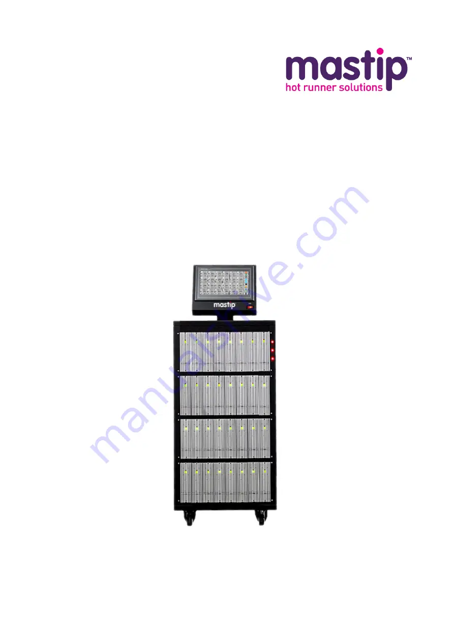
Page 3: ...TI controller series is made up of 3 different models of mainframes depending on the number of zones required These are referred to as CTI 100 CTI 200 and CTI 300 All the mainframes utilize the same t...
Page 4: ...rame are configured depending on the initial specification request and are fixed to the specific slot position 1 3 Specifications Model CTI 100 CTI 200 CTI 300 User Interface Full color LCD touch scre...
Page 5: ...Screw Position Signal DC 0 10V Screw Position Unit mm or inch Control Mode Auto Manual Time Resolution 1s or 0 1s or 0 01s Output Signal DC24V or AC220V or Relay contact Output Connector Various optio...
Page 6: ...Typical Power and Thermocouple Output Connector Wiring The system can be supplied with either European style or US style power and thermocouple mold connectors typically wired as follows custom wiring...
Page 7: ...or by a 0 10Vdc Screw Position source from the injection molding machine Valve Gate Input Wiring Valve Gate Output Wiring European style 24 pin series A Signal Pins Description Type Trigger Input 1 2...
Page 8: ...01 www mastip com Temperature Controller METICOM CTI Series Power Input Wiring The CTI temperature controllers can be connected to either 3 phase 4 wire Y type 200 240Vac or 3 phase 5 wire Y type 380...
Page 9: ...atches the local power supply The power specification label is located on the back cover of the mainframe s power input terminal block The label indicates the input voltage configuration that was prew...
Page 10: ...power connector cable and communication connector cable of HMI for any physical damage 2 2 Mounting the HMI only CTI 200 Series 1 Connect the HMI s power cable and communication cable to correspondin...
Page 11: ...rth cord to the ground terminal beside the input terminal block 7 Cover the plastic panel on the terminal block 8 Take up excess slack in cable and secure with strain relief clamp 9 Mount the metal co...
Page 12: ...cable is the same as on the mold Confirm that the sequential valve gate power output meets the requirement of the solenoid valves Confirm that the sequential valve gate trigger signal meets the requi...
Page 13: ...tem 10 Check that the controller is functioning correctly IMPORTANT When switching off the system wait 30 seconds before switching on again System communication issues can be experienced if the system...
Page 14: ...2 zone Actual Temperature PV resolution 0 1 can be selected on system setting page displayed in red in stop state e g No 3 zone if thermocouple is open 999 is displayed e g No 2 zone if zone is turne...
Page 15: ...ature control of all zones in Auto mode Standby Places the temperature control of all zones in Standby mode In this mode the target is 70 of setpoint PgUp View the previous page PgDn View the next pag...
Page 16: ...gger signal to test all valve gates control Login Logout Log in out the system to achieve the different security authority Gate Number Working Status Valve Gate Status Open Close or OFF when zone is s...
Page 17: ...Removing the USB disk from the system during a read or write operation could cause data corruption to the USB disk contents that could result in bad files or prevent the entire drive from being usable...
Page 18: ...ce displays Login Touch it to open the Login screen select the corresponding user group and input password to login the system In the status of the user login the main interface shows Logout Touch it...
Page 19: ...d related Set data save interval time All operations in global setting Initial password is 654321 for the user Engineer Administrators All authorities of Engineers Manage the users and authorities Sel...
Page 20: ...or Auto generate the Module s ID Administrators the user group name cannot be deleted All authorities Change Password You can change the password for the current user Authorized to Change Setpoint Eve...
Page 21: ...temperature in the cabinet of all modules and its zone number 5 2 4 System Data Saved Interval After the setting time the system saves the data automatically 0 min means not to save the data and you c...
Page 22: ...ing Remote stop control When the system receives an external stop signal it will stop running Remote standby control Standby delay time After the system receives an external standby signal it will wor...
Page 23: ...ou can divide all zones into up to 4 groups max 11 zones in each group the zones not appointed will be in the last group The groups will start to work one by one in turn When the system starts the fir...
Page 24: ...for each group e g If you need the next group will work when each zone s temperature is not less 5 than its target then you should set the tolerance to 5 for this group 4 Touch the Enable or Disable...
Page 25: ...hm to determine the required output power to hold the actual temperature value equal to standby temperature value 70 of setpoint Manual This type of control is an open loop system and requires no ther...
Page 26: ...etail Parameters for Each Zone Parameter Description Setpoint Target temperature full scale Alarm High High deviation alarm value When actual value Setpoint Alarm High zone alarms and shut off output...
Page 27: ...hen load current is higher than setting controller will limit it by decreasing the power output Parameter Description Filter To reduce the influence of interference The larger the value is the slower...
Page 28: ...ig 6 4 1 1 Global Config Parameters for all zones can be set all together 1 Click the parameter value to be set and then the keyboard will appear 2 Input the required value 3 Click OK to complete the...
Page 29: ...te the setting NOTE If there is no response when you click the parameter s value it means this parameter cannot be changed or the authority is not enough 6 4 2 Mold Patterns You can manage the mold pa...
Page 30: ...tern s Config Import 1 Click the Assigned Pattern s Config Import to enter the pattern files selected screen 2 Click to select a pattern 3 Click OK to import the parameters in the pattern file to the...
Page 31: ...l storage to the USB disk Pattern Name Pattern selector indicator blue unchecked green checked Quit back to the Global Config Pattern Management Screen 6 4 2 4 Comparison of Assigned Parameters 1 Ente...
Page 32: ...fferent authority can see different parameters 6 5 1 Non Login Status if everyone can change setpoint Change Setpoint by Save the change and quit the setting touch SET Run or Stop this zone touch Run...
Page 33: ...ch Run Stop Turn off or turn on this zone touch OFF ON Change Control mode of this zone in running state touch Auto or Manual Activate Boost function fast heating speed touch Boost and the power outpu...
Page 34: ...TICOM CTI Series And you can touch Exit to go back to the main interface 6 6 1 Present Curve real time 6 6 1 1 Select Zone ID to View On Present Curve Screen you can view max 6 zones 1 Click the ID nu...
Page 35: ...green checked The curve s color is same as the color of ID number 7 7 3 History Curve The system default setting is not saving the temperature data If you need to review the history curve or export th...
Page 36: ...COM CTI Series Each History Curve Screen can display 10 zones You can select the ID group to view or back to present curve by Quit 6 6 2 2 Select the Curve Display The box before the ID number is used...
Page 37: ...ard 2 0 hour based on the curve 6 6 2 4 Zoom In Zoom Out the Curve You can adjust the scale of X Y axis with the sliding bar to zoom in or zoom out the curve 6 6 2 5 View Other Zones You can view the...
Page 38: ...the time format should be same as the original one And then the End Time 6 7 1 2 Refresh the Record You can click Refresh to refresh the alarm records after selecting a new period 6 7 1 3 View More R...
Page 39: ...if the heater s power is large Over Temp PV temp is over high alarm value Alarm value Setpoint Alarm High Controller will shut off the output Check the controller the sensor Under Temp PV temp is und...
Page 40: ...ontroller will adjust output percent to 0 Check the sensor condition position and wiring Temp twinkling Communication between HMI and control module is failed Check the module and communication wiring...
Page 41: ...main interface Notes 1 Zone s output type is selected on modules with jumpers 2 Input Screw position unit can be mm or inch selected in screw position s setup calibration 7 1 Control Modes Auto This...
Page 42: ...position is T1 from the controller receives start trigger 3 Gates close after T2 time or screw position is T2 from the gates open 4 Gates open again after T3 time or screw position is T3 from the gate...
Page 43: ...ose after T4 time or screw position is T4 from the gates open 6 The controller waits a new start trigger Mode 1 The gate open close cycle will be terminated and gate close when the start trigger ends...
Page 44: ...mer from the zero time position 2 Gates open after T1 time or screw position is T1 from the controller receives start trigger 3 Gates close after T2 time or screw position is T2 from the gates open 4...
Page 45: ...gate open close cycle will be terminated and gate close 7 The controller waits the next new start trigger 7 3 Gate Open Close Trigger Modes You have two main options that you can use to set up gate o...
Page 46: ...ormally Input Type Start trigger modes selection Resolution Resolution for Time sec Screw position mm inch 7 5 Gate Setup Touch the Gate Status Open or Close on the main interface then you can enter G...
Page 47: ...3 Set screw forward back position click the value to call up small keyboard 4 Calibrate screw forward back position push the screw to forward position and touch Calibration forward next push the screw...
Page 48: ...cked Set T1 T4 click the value to call up small keyboard Back to main interface touch Exit 7 6 Preview the Setting Touch Graph on the main interface and then you can see the sequential chart of all ga...
Page 49: ...specified zone by Zone Setting You can Run or Stop a group of zones with the same background color by Global Config Sequential Valve Gate Control All zones start to work in Auto mode You can touch Ma...