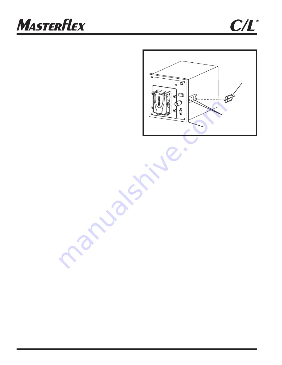
Installing Panel Mount
Mounting Brackets
The optional Mounting Brackets are used to attach the 1/4
DIN Case to a Mounting Rack. Use Mounting Brackets Part
No. 77120-03, (2/set).
1. Be sure the panel bezel is on the pump, then slide the
pump system through the front of the mounting rack.
2. Place a
Mounting Bracket,
Figure 6,
between the grooved
bracket retainers on one side of the Case and slide the
Mounting Bracket back to lock into the retainer grooves.
3. Tighten the bracket screw against the back of the rack to
hold the Pump System in place.
4. Repeat steps 2 and 3 for the second Mounting Bracket
on the opposite side.
Installing Rubber Feet
Four rubber feet are provided for operating the Pump System
on a bench or other flat surface and for stability when stacking
multiple units. The feet should be installed at the four corners
on the bottom of the unit. Remove the
protective paper from the adhesive surface of each foot
and press the foot firmly on the bottom surface about
one-eighth inch in from and parallel to the outer edges.
Connecting Primary Power
Depending on the Pump System model, primary power may
be 100-240V AC or 12V DC. The DC models can be
connected to any DC* supply and are not supplied with a
Universal Power Supply unit. Connect the External Power
Supply to the applicable input voltage source and
the output of the External Power Supply to the DC input
connector on the pump unit.
*Refer to Specifications for current supply voltage.
NOTE:
The Power Supply output connection is center
positive (+).
6
®
Backup Battery Connection
Terminals 1 and 2 on the rear panel Barrier Terminal Strip,
Figure 3
, provide a means for connecting a backup DC power
source. The positive (+) terminal is terminal 1. The negative
(–) terminal is terminal 2. Connection to these terminals would
usually be made only for emergency type operation in
conjunction with an External Power Supply, or a stand-alone
operation for the DC models.
NOTE:
Input voltage must not exceed 15V DC or equipment
may be damaged. A minimum of 11.0V DC is required for
proper operation.
Remote Start/Stop Connection
Terminals 3 and 4 on the rear panel Terminal Strip,
Figure 3
,
are used for remote start/stop operation. Pump direction and
speed are not remotely controllable. In non-remote operation,
these terminals are connected together by a Shorting Bar.
For remote control by switch closure, remove the Shorting Bar
and connect the two terminals of the remote control switch to
terminals 3 and 4. A closure of the remote control switch
contacts will start the Pump System. Opening the contact will
stop the Pump System.
Figure 6. Mounting Bracket Installation
Mounting
Bracket
Bracket
Retainers
Bezel


