background image


Page 20 


USING THE LENGTH STOP


     WARNING Before performing any 

assembly or adjustment, always 

disconnect from power source. Failure 

to unplug your saw could result in 

accidental starting causing serious 

injury. 

     WARNING To avoid risk of personal 

injury, if movement is tight or if there is 

play in the adjustment, have your saw 

serviced by an authorized service 

center before using or contact (866) 

902-9690 for assistance. 

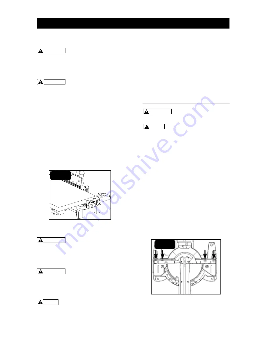
It is very convenient to get all same length 

work pieces by using the length stop. This 

length stop is located on the extension 

arms (Fig. 20). 

The length stop is a pivoted block. To 

using the length stop, press the lower part  

of its side face. It will turn to form a right 

angle to the table. 

To fold the length stop, gently push the 

upper part of it toward saw arm. It will 

return to original position. 


ACCURACY ADJUSTMENT 

     WARNING Before performing any 

assembly or adjustment, always 

disconnect from power source. Failure 

to unplug your saw could result in 

accidental starting causing serious 

injury. 

     WARNING To avoid risk of personal 

injury, if movement is tight or if there is 

play in the adjustment, have your saw 

serviced by an authorized service 

center before using or contact (866) 

902-9690 for assistance. 

     NOTE: The saw is factory set for 

accurate cutting. After assembling it, 

check for accuracy as directed in the 

following section of this manual. If 

shipping has influenced the settings, 

refer to specific procedures explained 

as following. 

There are 5 accuracy adjustments totally: 

(1) Squaring the blade to the fence. 

(2) Squaring the blade to the table. 

(3) Adjusting the blade to the miter table, 

45° bevel, 0° miter. 

(4) Bevel angle indicator adjustment. 

(5) Miter angle indicator adjustment. 

(1) SQUARING THE BLADE TO 

THE FENCE


     WARNING Failure to unplug your 

saw could result in accidental starting 

causing serious injury. 

     NOTE: To do accuracy adjustment, 

you will need the combination square 

(not supplied). 

Step 1: Unplug the saw. 

Step 2: Set the bevel and miter angles to 

0°. 

Step 3: Lower and lock the saw arm in the 

“Down” position. 

Step 4: Place the heel of a combination 

square against the blade body (not teeth) 

and the ruler of the square against the 

fence. 

Step 5: If the blade is not 90° to the fence, 

completely unscrew the fence-locking knob 

and remove the upper sliding fences. 

Step 6: Loosen four screws with hex key 

(not supplied) and rotate the fence until the 

square ruler is flush along its entire length. 

Retighten the hex-head bolts (Fig. 21). 

Step 7: Replace the upper sliding fences 

and reattach the fence-locking knobs. 


FIG. 20 


FIG. 21 


ASSEMBLY AND ADJUSTMENT 


Summary of Contents for 240-0021

Page 1: ...For more information or to ask questions Call Toll Free 866 902 9690 Monday Friday between 8 30 AM and 5 00 PM ET CAUTION To Reduce The Risk Of Injury User Must Read And Understand Operator s Manual S...

Page 2: ...afety symbols 3 Safety instructions 4 Electrical 8 Laser 9 Application 10 Specifications and features 12 Assembly and adjustment 15 Operation 23 Maintenance 30 Troubleshooting 31 Warranty 32 TABLE OF...

Page 3: ...side shields and a full face shield when operating this product Hand protection Wear gloves for handling saw blades and rough material recommendation that saw blades should be carried in a holder whe...

Page 4: ...cord to disconnect it from the socket Keep the cord away from heat oil and sharp edges SECURE WORK Use clamps or a vise to hold work when practical It s safer than using your hand and it frees both h...

Page 5: ...ete stop Make workshop kid proof with padlocks master switches or by removing starter keys Don t force tool It will do the job better and safer at the rate for which it was designed Never use saw blad...

Page 6: ...ate your saw on the floor or in a crouched position Only use the correct blades Use the correct blade size style and cutting speed for the material and the type of cut Do not use blades with incorrect...

Page 7: ...fingers to touch the terminal or the plug when installing or removing the plug from an outlet To reduce the risk of electric shock double insulated tools are equipped with a polarized plug one prong i...

Page 8: ...y object other than the work piece Always ensure that the laser beam is aimed at a sturdy work piece without a reflective surface Wood or rough coated surfaces are acceptable Bright shiny reflective s...

Page 9: ...the blade binds or stalls throwing the work piece back toward the operator Miter Cut A cutting operation made with the blade at any angle other than 90 to the fence No Hands Zone The area between the...

Page 10: ...g blade 6 mm hex key D 1pc Work piece clamp E 1pc Operator s Manual WARNING If any parts are damaged or missing do not operate this saw until the missing parts are replaced Failure to heed this warnin...

Page 11: ...8 pounds Cutting Capacities Inches 0 Miter x 0 Bevel 45 Miter x 0 Bevel 0 Miter x 45 Bevel 45 Miter x 45 Bevel Max Cross Cut 13 5 9 5 13 5 9 5 Max Depth of Cut 3 5 3 5 1 8 L 1 0 R 1 8 L 1 0 R Max Cros...

Page 12: ...Page 12 SPECIFICATIONS AND FEATURES FIG 2 FIG 3...

Page 13: ...cutting accuracy MITER LOCK HANDLE The miter lock handle securely locks the miter table at the desired miter angle MITER LATCH BUTTON When pushing the miter latch button down it will release the mite...

Page 14: ...ou have carefully inspected and satisfactorily operated the miter saw TRANSPORTING THE SAW WARNING Failure to unplug your saw could result in accidental starting causing serious injury WARNING This sa...

Page 15: ...e Step 2 Pull out the lever to disengage from the locking bolt and then rotate approximately turn clockwise Step 3 Release the lever to re engage with the locking bolt and rotate approximately turn to...

Page 16: ...g head To avoid the saw head tilting down suddenly due to its own weight hold the saw arm in place with one hand when loosening the bevel lock lever Step 3 Make sure the angle detent pin is in disenga...

Page 17: ...t in accidental starting causing serious injury WARNING To avoid risk of personal injury if movement is tight or if there is play in the adjustment have your saw serviced by an authorized service cent...

Page 18: ...the depth stop block Step 4 Plug the saw and press down the saw head to cut and check the depth adjust the cutting depth to requirement by turning the depth stop adjustment bolt Step 5 Tighten the lo...

Page 19: ...ll out the whole clamp to remove WARNING When using the work piece clamp included to secure the work piece clamp the work piece on one side of the blade only The work piece must remain unclamped on th...

Page 20: ...ng or contact 866 902 9690 for assistance NOTE The saw is factory set for accurate cutting After assembling it check for accuracy as directed in the following section of this manual If shipping has in...

Page 21: ...e combination square Due to tight checking place only use the combination Square s head NOTE To correct angle accuracy of the blade to the miter table either by squaring the blade to the table or by a...

Page 22: ...On Off trigger the lock off button will engage the safety switch automatically NOTE Make the On Off trigger childproof Insert a small padlock not included or cable with padlock through the holes in t...

Page 23: ...Step 7 Before turning the saw on lower the saw arm to make sure that the clamp clears the moveable safety guard and the saw arm Step 8 Squeeze On Off trigger Always allow the blade to reach full speed...

Page 24: ...orming any miter cuts the upper fence could be moved depending on your requirement Step 1 Unplug the saw Step 2 Set the bevel angle at 0 and turn the miter table to desired angle using either the mite...

Page 25: ...checked after setting the second angle Once the two correct settings for a particular cut have been obtained always make a test cut WARNING Never pull the saw toward you during a cut The blade can sud...

Page 26: ...is tool has multi slide bar of two sections Each section can be locked unlocked by its own locking knob Step 1 Unplug the saw Step 2 Loosen the lock nut rotate the depth stop adjustment bolt to the de...

Page 27: ...ng has a high top rear spring angle the section that fits flat against the ceiling of 52 and a bottom rear spring angle the section that fits flat against the wall of 38 Step 1 Unplug the saw Step 2 S...

Page 28: ...rench included to turn the threaded blade screw clockwise Remove the blade screw and the outer blade flange Step 7 Remove the blade wipe the blade flanges and spindle to remove any dust and debris put...

Page 29: ...frequent lubrications You will need to apply Automotive oil directly to the slide bars Light oil or pressurized light spray oil to the arm pivot shaft Light oil or pressurized light spray oil to the t...

Page 30: ...emedy Motor does not power on Brush worn Contact customer service center Brush sparks excessively when switch is released Brush worn damaged Replace brushes See MAINTENANCE chapter Blade hits table Mi...

Page 31: ...ears The warranty 1 Excludes expendable parts including but not limited to blades bits light bulbs and or batteries 2 Shall be void if this tool is used for commercial or and rental purposes And 3 Doe...

Page 32: ...Page 32 For more information or to ask questions Call Toll Free 866 902 9690 Monday Friday between 8 30 AM and 5 00 PM ET 2015 Menard Inc Eau Claire WI 54703 06 2015...

Reviews: