51
ITALIANO
ENGLISH
1) assicurarsi che la testata sia ben poggiata a terra,
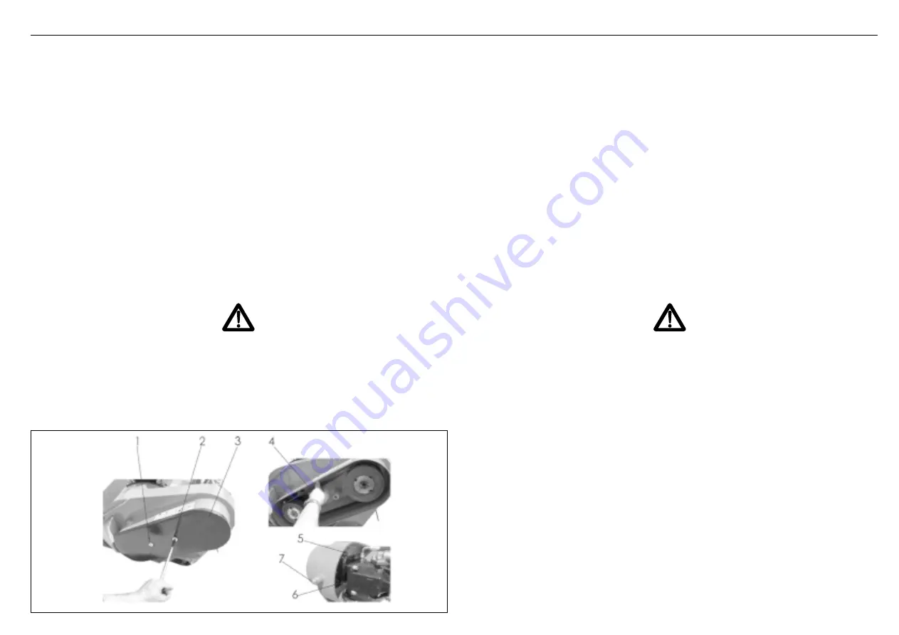
2) svitare le viti (1 Fig. 45) e (2 Fig. 45);
3) togliere il carter di protezione (3 Fig. 45);
4) applicare una moderata forza con le dita pollice e indice alla cinghia (4 Fig. 45) e verificare
che la torsione di 45
°
;
5) eventualmente regolare la tensione fino ad ottenere il risultato di cui al punto 4 agendo
sulle viti di regolazione (5, 6 Fig. 45) e quindi sulla (7 Fig. 45).
La cinghia deve essere sostituita ogni 500 ore, se non prima secondo lo stato di usura,
come di seguito descritto:
1) assicurarsi che la testata sia ben poggiata a terra;
2) svitare le viti (1, 2 Fig. 45);
3) togliere il carter di protezione (3 Fig. 45);
4) svitare le viti (5, 6, Fig. 45) e allentare il bullone (7 Fig. 45) fino a riuscire senza sforzo
a sfilare la cinghia;
5) sistemare sugli organi di trasmissione la nuova cinghia;
6) stringere la vite (7 Fig. 45) e avvitare le viti (5, 6 Fig. 45);
7) effettuare la registrazione della cinghia come sopra descritto.
4.7 SOSTITUZIONE DEI COLTELLI
PERICOLO
Durante queste operazioni assicurarsi che il motore del mezzo, sia tolta la chiave di
avviamento dal quadro, sia inserito il freno di stazionamento e la testata di taglio
sia appoggiata al terreno in posizione verticale.
Procedere alla sostituzione dei coltelli tenendo presente che i coltelli non devono
essere sostituiti parzialmente onde evitare che durante l’uso la testata di taglio
possa vibrare.
1) make sure that the head is resting firmly on the ground,
2) unscrew the screws (1 Fig. 45) and (2 Fig. 45);
3) remove the protective casing (3 Fig. 45);
4) apply a moderate force on the belt with the thumb and index finger (4 Fig. 45) and
make sure that the torsion is 45
°
;
5) if necessary, adjust the tension until obtaining the result indicated in point 4, using
adjuster screws (5, 6 Fig. 45) and then (7 Fig. 45).
The belt must be replaced after every 500 hours service or even sooner, depending on the
state of wear. Proceed as described below:
1) make sure that the head is resting firmly on the ground;
2) unscrew the screws (1, 2 Fig. 45);
3) remove the protective casing (3 Fig. 45);
4) unscrew the screws (5, 6, Fig. 45) and loosen the bolt (7 Fig. 45) until the belt can be
removed without forcing;
5) fit a new belt on to the transmission components;
6) tighten screw (7 Fig. 45) and screws (5, 6 Fig. 45);
7) adjust the belt as described above.
4.7 KNIFE REPLACEMENT
DANGER
During these operations, make sure that the vehicle’s engine is off, the ignition key
removed from the dashboard, the parking brake applied and the mowing head low-
ered to the ground in the vertical position.
Replace the knices, remebering that they must not be replaced partially as other-
wise the mowing head could vibrate as it operates.
Fig. 45


