background image

ENGLISH

SVENSKA

43

ITALIANO

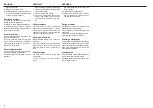
4.9 INCONVENIENTI, 

CAUSE E RIMEDI

 Inconvenienti 

Cause 

Rimedi

Trasmissione rumorosa in prossimità dei dispositivi di sollevamento.

Zappatrice rumorosa mentre lavora.

Assorbimento troppo elevato di potenza con terreno secco.

Proiezione elevata di terreno nella parte posteriore della zappatrice.

Assorbimento troppo elevato di potenza con terreno umido.

Eccessivo sminuzzamento del terreno.

Scarso sminuzzamento del terreno. 


Intasamento del rotore. 


Non corretta cinematica degli attacchi di sollevamento.


Altezza dei dispositivi di sollevamento troppo elevata. 


La zappatrice lavora troppo inclinata in avanti o all’indietro.

Insuffi ciente stabilità laterale della zappatrice.

Volume di terreno lavorato troppo elevato.

Profondità di lavoro troppo elevata.

Zappe usurate.


Eccessiva velocità di rotazione del rotore (versioni con cambio).

Errato posizionamento della lamiera livellatrice.

Volume di terreno lavorato troppo elevato.

Profondità di lavoro troppo elevata.

Intasamento della lamiera livellatrice.

Eccessiva velocità di rotazione del rotore (versioni con cambio).

Lamiera livellatrice troppo chiusa.


Velocità di avanzamento troppo bassa. 

Eccessiva velocità di rotazione del rotore (versioni con cambio).

Lamiera livellatrice troppo aperta.


Velocità di avanzamento troppo elevata.

Terreno troppo umido. 

Bassa velocità di rotazione del rotore (versioni con cambio).

Terreno troppo umido. 

Lamiera livellatrice troppo chiusa. 

Velocità di avanzamento troppo elevata.

Le zappe trattengono il terreno lavorato. 

Presenza di erba molto alta e/o di residui troppo lunghi.

Posizionare l’attacco terzo punto parallelamente ai bracci inferiori

di sollevamento. 

Limitare la corsa del sollevamento.

Se il problema persiste disinnestare la PDF al momento del

sollevamento. 

Allungare o accorciare l’attacco terzo punto in modo che il piano su-

periore della zappatrice sia parallelo al terreno da lavorare (gli attacchi 

della PDF del trattore e della zappatrice devono essere paralleli). 

Stabilizzare la zappatrice agendo sui tiranti dei bracci inferiori di

sollevamento.

Diminuire la profondità di lavoro regolando le slitte di profondità della 

zappatrice.

Effettuare la sostituzione completa del set di zappe per garantire 

l’equilibratura del rotore.

Ridurre la velocità del cambio. 

Modifi care la posizione della lamiera livellatrice. 

Diminuire la profondità di lavoro regolando le slitte di profondità della 

zappatrice.

Sollevare la lamiera livellatrice per agevolare il defl usso del terreno. 

Ridurre la velocità del cambio. 

Sollevare la lamiera livellatrice per ridurre la frantumazione delle

zolle.  

Aumentare la velocità di avanzamento. 

Ridurre la velocità del cambio. 

Abbassare la lamiera livellatrice per una migliore frantumazione delle 

zolle. 

Ridurre la velocità di avanzamento. 

Evitare di lavorare terreno troppo umido. 

Aumentare la velocità del cambio. 

Evitare di lavorare terreno troppo umido. 

Sollevare la lamiera livellatrice. 

Ridurre la velocità di avanzamento. 

Ridurre da 6 a 4 le zappe per ogni fl angia del rotore. 

Evitare di lavorare con presenza di erba molto alta o di residui molto 

lunghi, eventualmente pulire bene ai lati del rotore ciò che si è fermato 

sui supporti per evitare il loro surriscaldamento. 

Summary of Contents for F07010128

Page 1: ...ountries G ller f r EU l nder Gilt f r EU Mitgliedsl nder V lido para Pa ses UE L USO E MANUTENZIONE PARTI DI RICAMBIO USE AND MAINTENANCE SPARE PARTS ANV NDNING OCH UNDERH LL RESERVDELAR MASCHIO GASP...

Page 2: ...n r f rsedd med en m rkskylt A Fig 3 som anger f ljande uppgifter 1 Tillverkarens adress 2 Typ av maskin 3 Typ av maskin 4 Serienummer 5 Tillverknings r 6 Standardvikt Vi rekommenderar att ni skriver...

Page 3: ...ntroll av lyftkapacitet och stabilitet hos traktorn med monterat redskap 23 3 6 Kardanaxel 24 3 7 Arbetsdjup 29 3 8 Kedjesp nnare 30 3 9 Knivar 30 3 10 Justering av F rflyttning i Sidled 31 3 11 Under...

Page 4: ...el of acoustic power LwA A dB 96 1 BULLERNIV Avl sningar av buller utan belastning UNI EN 1553 2001 Ljudtrycksniv LpAm A dB 81 1 Ljudeffektsniv LwA A dB 96 1 1 1 DATI TECNICI 1 1 TECHNICAL DATA 1 1 TE...

Page 5: ...llare 3 Trepunktskoppling 4 Lyftbygel p jordfr s 5 Hastighetsreducerare 6 Sidotransmissionsenhet 7 Nivelleringsplatta 8 Slid f r justering av arbetsdjup 9 Rotor med hackknivar 10 Nedre kopplingspunkt...

Page 6: ...rt och utan tillr cklig kunskap eller utbildning har inte till telse att anv nda maskinen Anv ndaren r ansvarig f r att se till att maskinen fungerar som den ska samt f r att byta ut och reparera dela...

Page 7: ...ENGLISH SVENSKA 7 ITALIANO Fig 3 1 A 7 16 10 15 3 2 8 17 19 18 14 12 4 6 13 20 11 9 5 20...

Page 8: ...stance from the ma chine 6 Danger of injury to the hands Never remove the guards while the parts are mowing Wait until all mov ing components have completely stopped 7 Danger Keep away from the cardan...

Page 9: ...tion and complete ANY CLAIMS FOLLOWING THE RE CEIPT OF DAMAGED GOODS SHALL BE PRESENTED IN WRITING WITHIN 8 DAYS FROM RECEIPT OF THE GOODS THEMSELVES FROM YOUR LOCAL DEALER The purchaser may only make...

Page 10: ...ignal warns when serious injuries death or long term health risks could be caused by failure to correctly carry out the described op erations CAUTION This signal warns when dam age to the machine coul...

Page 11: ...potential dangers when using the machine and are able to avoid them AUTHORIZED SERVICE CENTER The authorized Service Center is a structure legally authorized by the manufacturer which disposes of per...

Page 12: ...front part of the tractor in order to balance the weights on the axles themselves 9 The coupled implement may only be controlled through the cardan shaft complete with the necessary safety devices for...

Page 13: ...and brak ing capacity may be even notably influenced by the presence of a towed or mounted implement 21 Always take care of the centrifugal force exercised by the furthered po sition of the center of...

Page 14: ...acturer 33 Frequently and periodically check the cardan shaft guard It must always be in an excellent condition and well welded 34 Take great care of the the cardan shaft guard both in the transport a...

Page 15: ...selected running rate cor responds to the permissible value Never exceed the recommended maximum rate 39 Never engage the pto when the en gine is off 40 Always disengage the pto when the cardan shaft...

Page 16: ...ned Re tighten them if necessary 47 Always place adequate supports un der the implement when servicing the machine or replacing the hoe blades with the implement raised 48 Before working on the cuttin...

Page 17: ...to use a system of hoisting with a crane and cables or chains of adequate capacity hooking onto the oachine at the hoisting points marked with the hook symbol 16 Fig 3 CAUTION Before proceeding to th...

Page 18: ...e for the mass which must be blocked see Technical Features for the weight The cables must be firmly fastened to the machine and pulled taut to the anchorage point on the platform Once transport has b...

Page 19: ...s important to remember that road holding steering and braking capacities may be even considerably influenced by a mounted or towed implement When mounted or semi mounted imple ments cover the tractor...

Page 20: ...ject to wear and deteriora tion are fully efficient Check the machine is correctly po sitioned for obtain the rigth working depth WARNING The accident prevention guards are delivered dismantled for sh...

Page 21: ...types of hitches find the best position for the machine by moving the plates 1 Fig 7 along and inserting the pin 2 Fig 7 in the holes corresponding to the correct diameter for the tractor s parallel a...

Page 22: ...ontal direction 3 Engage the cardan shaft and check that it is perfectly locked on the pto Check that the guard is free to turn and fix it with the relative latch Remove the cardan shaft support chain...

Page 23: ...g The effect of the levelling plate on the soil can be increased or decreased depending on the position estab lished by the split pin 2 Fig 11 in the various holes in the ram tube 3 Fig 11 The split p...

Page 24: ...hitch hole and center of gravity of machine cm Fig 1 3 6 CARDAN SHAFT Cardan shaft adaption The Cardan shaft supplied with the ma chine is of standard length Therefore it might be necessary to adapt t...

Page 25: ...13 of the housing s grooved ring nut parallel to the ground Inspections at work The two angles Fig 13 formed by the fork axes and the axis of the slid ing tubes will be equal and must not exceed 10 Th...

Page 26: ...per hitch bar is as parallel as possible to the lower bars of the hitch If this is not sufficient correct the way the top link of the hitch couples to the trac tor or machine as necessary or at least...

Page 27: ...with safety clutch to protect the transmission components of the machine from stress and or excessive overloads The tilt of the cardan shaft must not ex ceed 10 degrees Fig 5 The clutch is already pre...

Page 28: ...h a safety bolt that is set for an average force Whenever unduly re sistant obstacles cause the bolt to shear it must be replaced by a new bolt of the same size and material If the bolt inserted in ho...

Page 29: ...atically engaged again by reducing the rpm rate of the PTO CAUTION Avoid frequent and lengthy over loads The driveline is supplied calibrated by the Manufacturer Do not tamper with the device if op er...

Page 30: ...hoe blades with which the machine is equipped can work soils of normal conformation Check the degree of wear and condition of the hoe blades each day If the blades should accidentally bend or break d...

Page 31: ...de ways in relation to the three point hitch This makes the implement extremely versatile during the various work condi tions Use of the hexagonal drive shaft allows the cultivator unit to quickly sli...

Page 32: ...0 rpm As well as holding the earth that has already been hoed by the hoe blades the levelling blade helps to produce a well levelled and smooth surface after hoeing If the levelling blade is raised th...

Page 33: ...corners while the implement is soil work ing Never work in reverse Fig 28 29 Always raise the implement in order to reverse or change direction During transport or whenever the im plement must be rais...

Page 34: ...animals in the field of action of the machine The operator must also pay attention to the above 3 13 PARKING WARNING Comple with the following instructions in order to ensure that the machine remains...

Page 35: ...to it proceed more slowly The earth is too finely broken up a Raise the levelling blade b Increase the forward moving speed of the tractor The earth is not broken up finely enough a Lower the levellin...

Page 36: ...ms The machine does not hoe to the same depth over the whole width e g if it hoes too deeply on the right side shorten the right arm of the lift bars and regulate the position of the right hand skid W...

Page 37: ...tions in relation to the type of service a more or less dusty environment seasonal factors etc In the case of heavy duty conditions the maintenance operations should obviously be more frequent All ope...

Page 38: ...8 hours service In particular you are advised to fully tighten all the screws and bolts on the machine after having checked the hoe blades for wear 4 2 EVERY 8 WORK HOURS Grease the cardan shaft cros...

Page 39: ...it is also advisable to demount and clean the clutch disks if the cardan shaft has a clutch Check the tightening of the clutch springs 4 5 STORAGE Proceed in the following way at the end of the season...

Page 40: ...ved if the machine should be scrapped Remember that the Manufacturer is always at your disposal for any as sistance or spare parts as may be required 4 6 DISMANTLING AND ELIMINATION OF USED OILS In ca...

Page 41: ...a fettsm rjningspunkter rekommenderar vi SM RJFETT AV TYP AGIP GR MU EP 2 eller motsva rande Konsultera sista omslagssidan f r specifikationer Nota Non superare le quantit d olio prescritte Note do no...

Page 42: ...ry 50 hours Var 50 e timme Alle 50 Betriebsstunden Cada 50 horas 400 h Ogni 400 ore Every 400 hours Var 400 e timme Alle 400 Betriebsstunden Cada 400 horas 400 h 50 h 8 h 8 h 50 h 400 h 1 CONTROLLARE...

Page 43: ...no lavorato Presenza di erba molto alta e o di residui troppo lunghi Posizionare l attacco terzo punto parallelamente ai bracci inferiori di sollevamento Limitare la corsa del sollevamento Se il probl...

Page 44: ...nei bloccati fra le zappe Zappe montate in modo errato senza la disposizione elicoidale o con il bordo non tagliente che penetra per primo il terreno Zappe usurate o rotte Deformazione del rotore dovu...

Page 45: ...point hitch parallel to the lower lifting links Limit the lifting travel If the fault persists disengage the PTO as the machine starts to lift Lengthen or shorten the third point hitch so that the upp...

Page 46: ...otor warped due to blows received in the central part from foreign bodies during work Depth skids adjusted incorrectly Insufficient tractor power Soil too hard Cultivator blades dig into the soil to a...

Page 47: ...rbetade jordklumparna Mycket h gt gr s och eller f r l nga plantrester Placera trepunktslyftet parallellt med de nedre dragstagen Begr nsa lyftr relsen Koppla ur kraftuttaget under lyftmomentet om pro...

Page 48: ...a omg ngar Minska k rhastigheten Reglera medarna f r arbetsdjup igen Reglera de nedre dragstagen igen Fr mmande f rem l har fastnat mellan knivarna Felaktigt monterade knivar den spiralformade profile...

Page 49: ...nge ritningsnummer och motsvarande referensnummer Beskrivning av reservdelen och antal som beh vs Transportmedel Om denna post inte r specificerad v ljer tillverkaren det effektivaste och snabbaste tr...

Page 50: ...AGIP GR MU EP 2 entspricht den folgenden Normen La grasa AGIP GR MU EP 2 satisfa los siguientes normas DIN 51825 KP2K L olio AGIP ROTRA MP soddisfa le seguenti specifiche AGIP ROTRA MP oil complies wi...

Reviews: