ENGLISH
SVENSKA
22
ITALIANO
A questo punto, procedere come se-
gue:
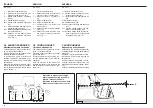
1) Accostare le parallele del sollevatore
ponendole all’interno delle piastre (1
Fig. 7), inserire il perno (2 Fig. 7) nel
foro predisposto e bloccare con le
copiglie a scatto.
2) Bloccare le parallele del sollevatore
con le apposite catene e tenditori pa-
ralleli sul trattore. Tale accorgimento
deve essere messo in atto per evitare
qualsiasi spostamento, in senso oriz-
zontale, della macchina.
3) Innestare l’albero cardanico e assicu-
rarsi che sia perfettamente bloccato
sulla presa di forza. Verifi care che la
protezione ruoti liberamente e fi ssarla
con l’apposita catenella.
Rimuovere il sostegno/catenella
dall’albero cardanico (2 Fig. 2) e ripor-
lo fi ssandolo nell’apposito aggancio.
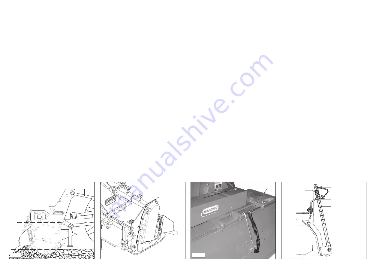
4) Collegare il terzo punto superiore ed
effettuare una corretta regolazione
con il tirante (1 Fig. 8) verifi cando che
il piano superiore della macchina (A
Fig. 8) risulti parallelo al piano terra
(B Fig. 8).
Ciò è molto importante allo scopo di
ottenere il parallelismo tra l’asse della
macchina e quello della presa di forza
del trattore. Operare in queste condi-
zioni signifi ca limitare le sollecitazioni
sulla presa di forza stessa e prolun-
gare la durata dell’albero cardanico e
della macchina stessa.
Now proceed in the following way:
1) Near the lift bars, setting them in the
most suitable plates (1 Fig. 7). Insert
the pin (2 Fig. 7) into the relative hole
and lock in place with the snap-in split
pins.
2) Lock the lift links using the relative
chains and couplings parallel to the
tractor.
This operation must be carried out to
prevent the machine from moving in
a horizontal direction.
3) Engage the cardan shaft and check
that it is perfectly locked on the pto.
Check that the guard is free to turn
and fi x it with the relative latch.
Remove the cardan shaft support/
chain (2 Fig. 2) and re-position it by
fi xing it on the relative hook.
4) Connect the upper third-point and
correctly regulate by means of the
adjuster (1 Fig. 8), checking that the
upper surface of the machine (A Fig.
8) is parallel to the ground (B Fig. 8).
This is very important since it achieves
parallelism between the axis of the
machine and that of the tractor pto.
When the implement operates in these
conditions, there will be less stress on
the pto itself while the cardan shaft
and implement will be much less
subject to wear.
innanför plattorna (1 Fig. 7), sätt i
tappen (2 Fig. 7) i det avsedda hålet
och lås fast med de snäppförslutande
blockeringsstiften.
2) Lås fast lyftarmarna med hjälp av
de tillhörande kedjorna och paral-
lella spännanordningarna på traktorn.
Detta moment måste utföras för att
undvika att maskinen förfl yttar sig
horisontalt.
3) Koppla till kardanaxeln och säkerställ
att den är ordentligt fastlåst på kraftut-
taget. Kontrollera att skyddet roterar
fritt och fäst det med den tillhörande
kedjan.
Ta bort stödet/kedjan från kardan-
axeln (2 Fig. 2) och sätt tillbaka den
genom att fästa den på den avsedda
kroken.
4) Anslut den övre tredje-punkten och
justera den korrekt med hjälp av
reglerstaget (1 Fig. 8) och kontrollera
att maskinens övre yta (A Fig. 8) är
parallell med marken (B Fig. 8).
Detta är mycket viktigt för att nå
parallellitet mellan maskinens axel
och kraftuttagets axel på traktorn.
Om redskapet arbetar under dessa
förhållanden, begränsas belastningen
på själva kraftuttaget och och kardan-
axeln och maskinen utsätts för mindre
slitage och håller längre.
Fig. 8
Fig. 9
1
A
B
2
3
1
4
Fig. 11
1
Fig. 10


