3.
System Operation
User Manual VS-104-3GSDI – V1.0
Page 15 of 67
3/2016
Snapshot
Capture video images and save them as BMP or JPEG files.
Talk
Transfer audio from the PC microphone to the encoder.
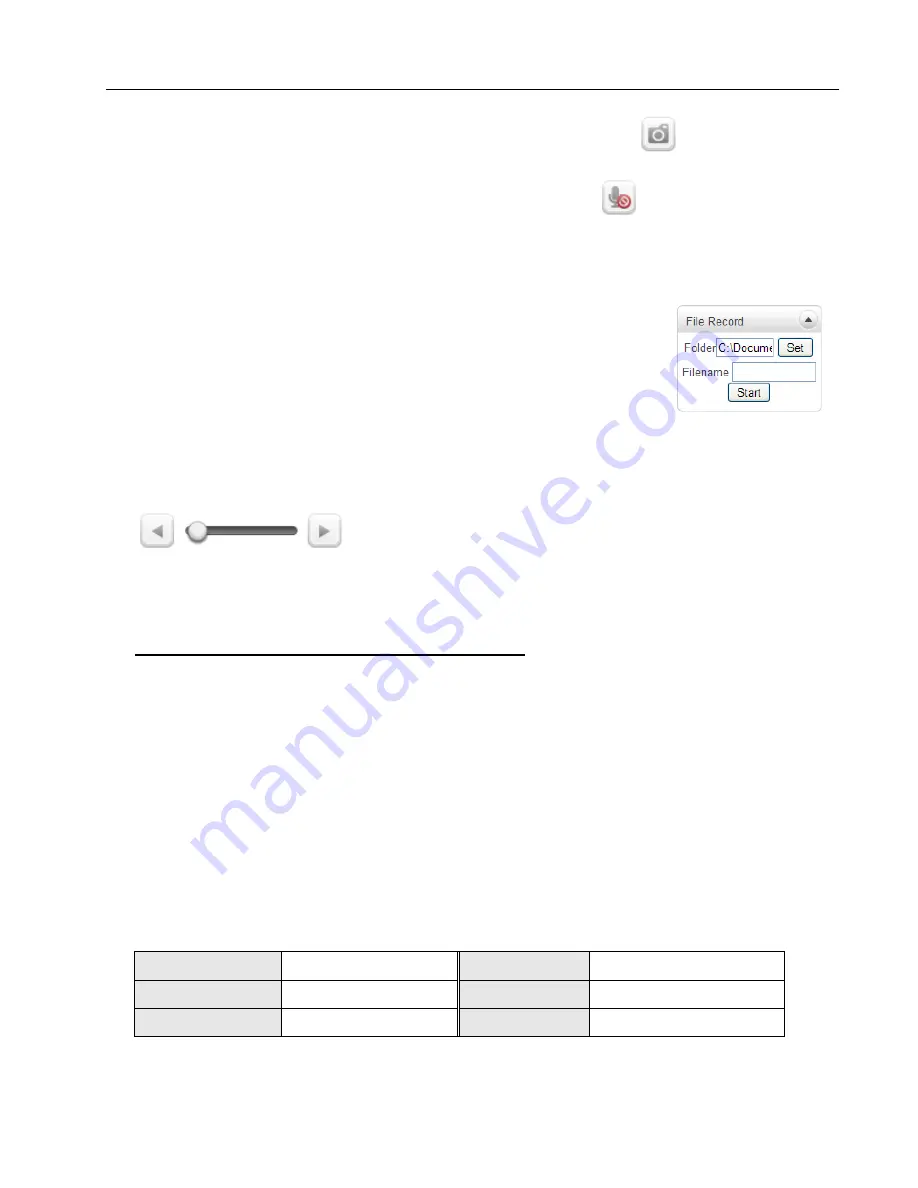
File Record
Recording to an AVI file on Live View page is available. AVI files are generated in the
specified folder or in specified file name on the PC where the web browser is running.
1.
Press “
Set
” button to select folder or create a new folder.
Enter the file name on Filename field.
2.
Press
“Start”
button to start recording.
3.
Press
“Stop”
button to end recording.
4.
AVI file named “
IP address_hh_mm_ss”
or
“
File name_IP address_hh_mm_ss”
will be generated in the
specified folder depending on whether the path specified a folder or a prefix of the file
name.
Display Buffer
Set the number of video frames to be buffered before being
displayed on web browser. Larger values result in
smoother video by sacrificing the latency. A setting of 10 ~ 15 frames can be generally
used for most situations.
Video Monitoring with Decoder System
When the Video Encoder’s IP Address is set in the Remote IP Address section of the
Decoder, the Decoder System will connect to the Encoder and start receiving the video
images. Normally, a monitor connected to the decoder will display video images.
3.2 Initialization of IP address
If a System IP Address is lost, the system can be reset to the System Default IP
Address using the Reset Button to the left of the LED lights.
1. While system is in operation, press the reset button for more than 5 seconds.
2. The system will reboot automatically.
3. Once the system reboots, IP Address will be set to the System Default as below:
IP Mode
Fixed IP
IP Address 192.168.10.100
Subnet Mask 255.255.255.0
Gateway
192.168.10.1
Base Port
2222
HTTP Port
80


