


9
4.2 PIPING
•
Use provided tubing of specified size for connection. Connect tubing securely
to prevent leakage of chemical and the entrance of air. Since plastic nuts are
used for fittings, they should not be tightened excessively (i.e. hand tighten
only). NPT suction and discharge valves must
NOT
be over tightened. Hold
fitting in place while adding piping and fittings. NPT suction and discharge
valves should only be tightened 25 to 35 in. lbs. (4.5-6.3 kg/cm).
•
If the air bleed valve assembly is being used, a return line (tubing) should be
securely connected and routed back to the storage tank.
To avoid possible
injury from chemicals do not attempt to prime using a bleed valve without
installing a return line.
•
When pump is shelf mounted or top mounted on tank, suction tubing should
be kept as short as possible.
•
To maintain metering performance, a backpressure/injection valve is provided.
The spring in the standard injection valve typically adds 17 - 20 PSI (1.17 - 1.38
BAR) to the line pressure, with the exception of the H8 pump, which adds 8 - 10
PSI (.55 - .69 BAR). The injection valve must be installed in the discharge line.
Best practice is to install the injection valve at the point of chemical injection.
•
If the discharge tubing is going to be exposed to direct sunlight, black tubing
should be used instead of the standard white translucent tubing supplied with
each pump. To obtain, contact supplier.
•
To prevent clogging or check valve malfunction always install a strainer
assembly to the end of the suction tubing (Figure 5). This foot valve/strainer
assembly should always be installed 1 to 2 inches (2-5 cm) above the bottom
of the chemical tank. This will help prevent clogging the strainer with any solids
that may settle on the tank bottom. The chemical tank and foot valve/strainer
should be cleaned regularly, to ensure continuous trouble free operation. If
the chemical being pumped regularly precipitates out of solution or does not
dissolve easily or completely (e.g. calcium hydroxide), a mixer should be used
in the chemical tank. These are readily available in many motor configurations
and mounting. To obtain, contact supplier.
•
A flooded suction (tank liquid level always at a higher
elevation than the pump) is recommended when pumping
solutions such as sodium hypochlorite (NaOCl),
hydrogen peroxide (H
2
O
2
), etc., which are likely to
produce air bubbles. Maintaining a low liquid temperature
will also help eliminate this problem.
•
Pipe corrosion can result if dilution at the injection point
does not occur rapidly. This problem is easily prevented
by observing this simple rule: install injection fitting so
that the end is in the center of the flow stream of the line
being treated. Trim injector tip as required. See Figure
6. Note: Extended injection assemblies are available for
large water lines. Consult your supplier for more
information.
FIGURE 6
16
•
When the “ON” signal pulse is input, the pump operates one stroke
and the fluid is discharged. In addition, the pump can be operated
continuously at a rate of up to 125 strokes/min. by repeated input of
“ON” and “OFF” signals.
•
After receiving an input signal, the pump generates the necessary
power pulse to actuate the solenoid. The external signal input is
debounced by the pump circuit. The pump will not stroke in response
to a spurious or erratic input signal that follows at a rate greater than
125 spm. If the external signal rate exceeds 125 spm, the pump will
stroke at half the external signal rate to prevent overdosing and to
protect the pump from overheating.
•
The input signal must be in the form of closure of a mechanical relay,
other mechanical switching device, or of a solid-state switching
device. Voltage signals are prohibited. The switching resistance of
either mechanical or solid-state devices must be 100 ohms or below
when ON and 1 megohm or above when OFF. If any type of solid-state
device is employed, it must be installed with proper polarity, if required
for the device; and leakage current must not exceed 200 microamperes
to prevent false triggering in the OFF state.
•
Cycle rate of the input signal should not exceed 125 times per minute.
•
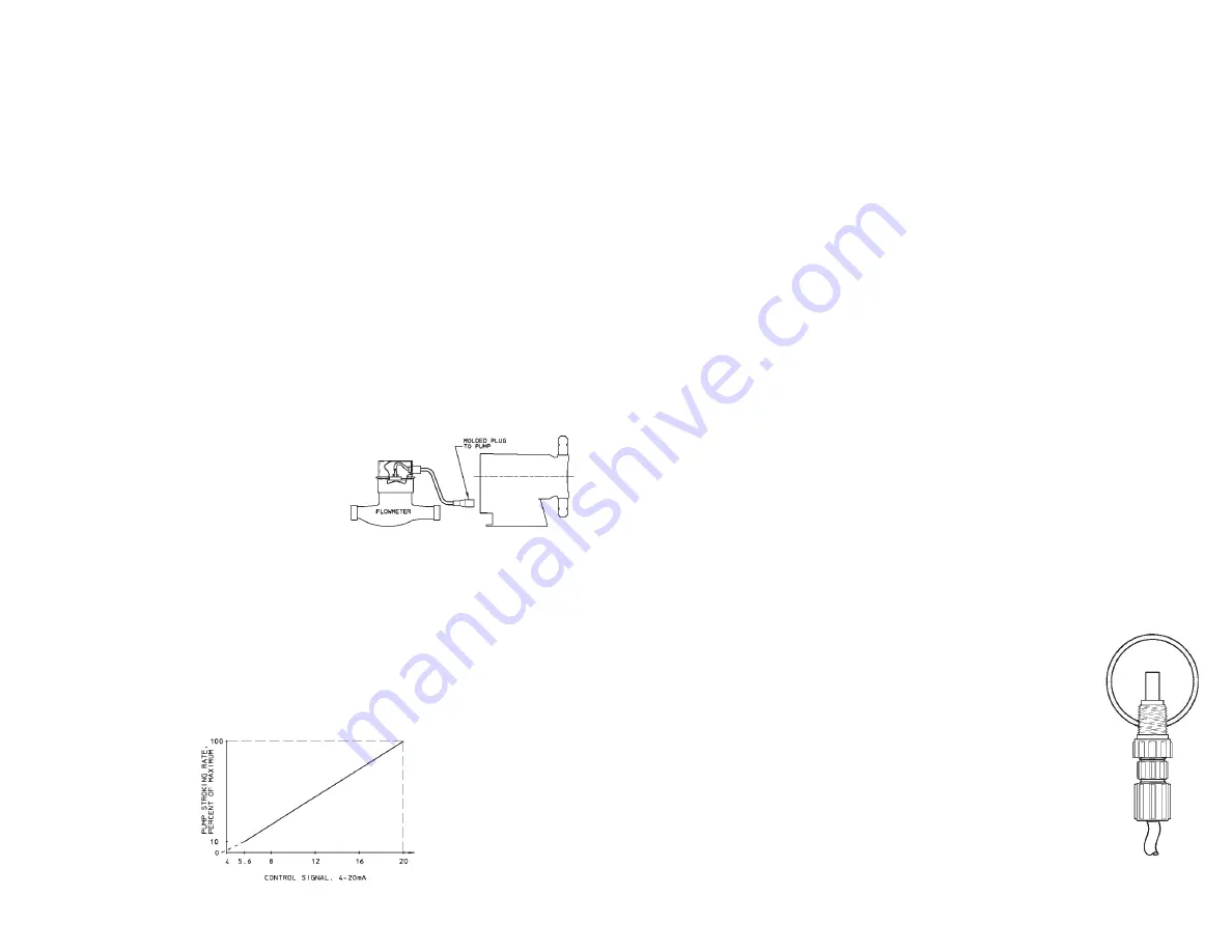
Typical wiring is shown at right
for use with switch closure
flowmeters. (Figure 12)
•
10 millisecond contact time re-
quired for each “ON” input sig-
nal.
5.5.3 4-20mA DC INPUT FUNCTION (E Plus only)
The pump’s stroke rate can also be controlled by a 4-20 mA DC signal to the
terminal marked [4-20 mA].
•
For the 4-20 mA input to have any effect on the pump output rate, the
AUTO/OFF/MANUAL switch must be in the AUTO position.
•
The 4-20 mA input signal affects the pump’s outputs as per the graph
below:
FIGURE 12
FIGURE 13
Summary of Contents for MATD 9500 XT
Page 4: ......
Page 7: ...9500 Control Dimensions Page 4 MATD 9500 XT MANUAL ...
Page 11: ...Page 8 ...
Page 19: ...Page 16 WATER CONDITIONER FLOW DIAGRAMS MATD 9500 XT MANUAL ...
Page 20: ...Page 17 WATER CONDITIONER FLOW DIAGRAMS MATD 9500 XT MANUAL ...
Page 21: ...Page 18 WATER CONDITIONER FLOW DIAGRAMS MATD 9500 XT MANUAL ...
Page 40: ...9500 Power Head Assy 61501 3200XT 9_REVA Page 37 MATD 9500 XT MANUAL ...
Page 42: ...9500XT Wiring 42140_2750XT_2850XT_REVA 0_2750XT_2850XT_REVA Page 39 MATD 9500 XT MANUAL ...
Page 43: ...Page 40 9100 9500 MATD 9500 XT MANUAL ...
Page 44: ...Page 41 9500 MATD 9500 XT MANUAL ...
Page 45: ...Page 42 9500 Control Valve Assembly MATD 9500 XT MANUAL ...
Page 46: ...Page 43 Second Tank Assemblies MATD 9500 XT MANUAL ...
Page 47: ...Page 44 Second Tank Assemblies MATD 9500 XT MANUAL ...
Page 48: ...Page 45 Meter Assemblies MATD 9500 XT MANUAL ...
Page 49: ...Page 46 Meter Assemblies MATD 9500 XT MANUAL ...
Page 50: ...Page 47 3 4 1 or 1 1 2 Paddle Wheel Meter Cap Assembly MATD 9500 XT MANUAL ...
Page 51: ...Page 48 Brine Valve Systems 1600 and 1700 Series MATD 9500 XT MANUAL ...
Page 52: ...Page 49 9500 2350 Safety Brine Valve MATD 9500 XT MANUAL ...
Page 53: ...Page 50 ...
Page 54: ...Page 51 Troubleshooting MATD 9500 XT MANUAL ...


