


7
3.2 MATERIALS OF CONSTRUCTION cont'd.
Consult a Chemical Resistance Guide or Supplier for information on chemical
compatibility.
Various manufacturers of plastics, elastomers and pumping equipment publish
guidelines that aid in the selection of wetted materials for pumping commercially
available chemicals and chemical compounds. Two factors must always be
considered when using an elastomer or plastic part to pump chemicals. They are:
•
The temperature of service: Higher temperatures increase the effect of chemi-
cals on wetted materials. The increase varies with the material and the chemical
being used. A material quite stable at room temperature might be affected at
higher temperatures.
•
Material choice: Materials with similar properties may differ greatly from one
another in performance when exposed to certain chemicals.
4.0 INSTALLATION
The metering pump should be located in an area that allows convenient connections
to both the chemical storage tank and the point of injection. The pump is water
resistant and dust proof by construction and can be used outdoors, however,
do not
operate submerged.
Avoid continuous temperatures in excess of 104
°
F (40
°
C). To
do otherwise could result in damage to the pump.
4.1 MOUNTING
Typical mounting arrangements are shown in Figures 3, 4, and 5.
Important:
Injection point must be higher than the top of the solution supply
tank to prohibit gravity feeding, unless suitable backpressure is
always present at the injection point. Installation of an antisiphon
valve will prohibit gravity feeding.
•
For wall or shelf mounting refer to Figure 3. Connect suction tubing to suction
valve of chemical pump. Suction valve is the lower valve. Tubing should be
long enough so that the foot valve/strainer assembly hangs about 1-2 inches
(2-5 cm) above the bottom of chemical tank. To keep chemical from being
contaminated, the tank should have a cover.
18
•
If the pump has been out of service for a month or longer, clear the pump head
valve assemblies by pumping fresh water for approximately 30 minutes. If the
pump does not operate normally after this “purging run”, replace cartridge
valve assemblies.
6.2 DISASSEMBLY AND ASSEMBLY
DIAPHRAGM REMOVAL
Flush pump head and valve assemblies out by running pump with water or other
suitable neutralizing solution. Wash outside of pump if chemical has dripped on
pump. Set stroke length knob of pump to 0% and unplug pump.
Depressurize the system and disconnect tubing or piping from the pump. Remove
the four pump head screws and then remove the pump head assembly.
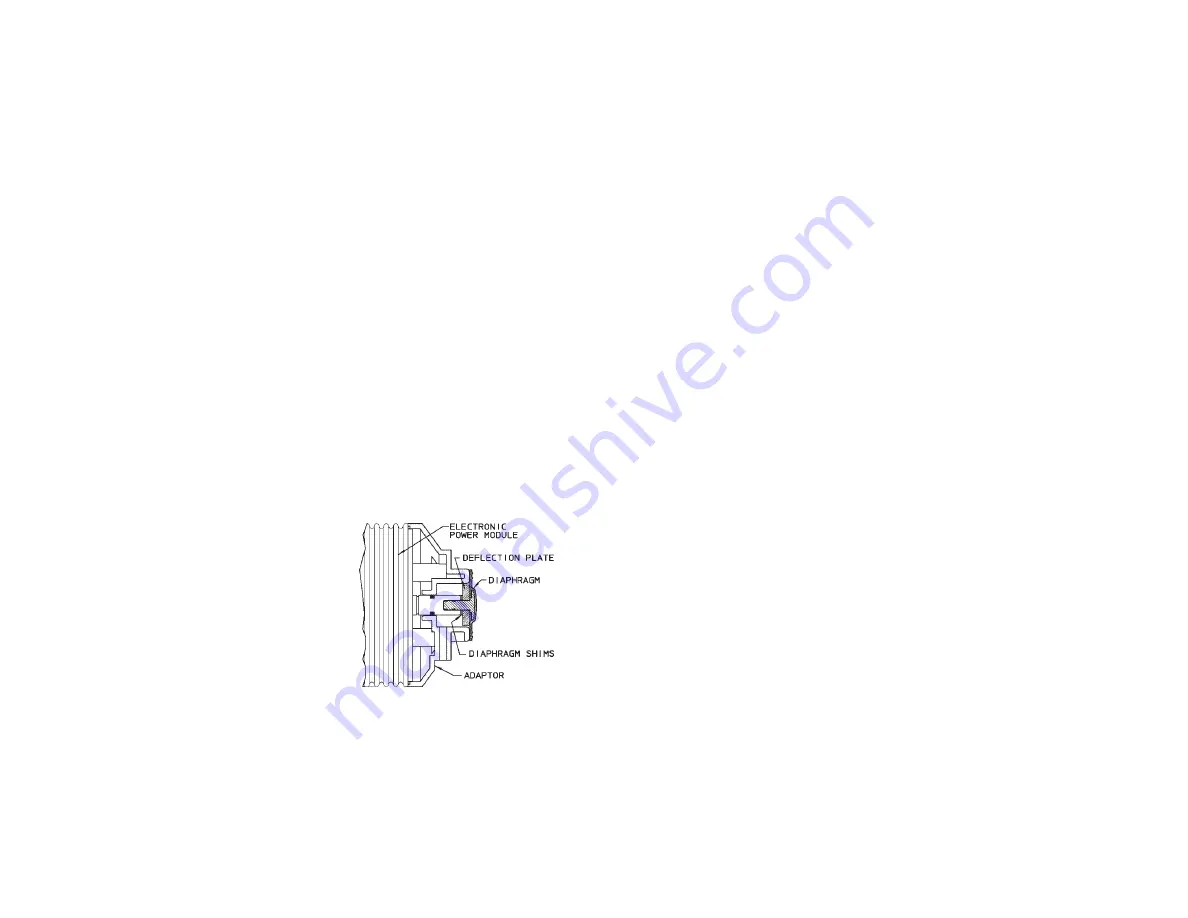
Remove the diaphragm by grasping it at the outer edge and turning it counter
clockwise until it unscrews from the electronic power module (EPM). Don’t lose
the deflector plate or diaphragm shims which are behind the diaphragm, they are
needed for re-assembly. Note shim quantity may be from 0 to 2.
Inspect diaphragm, if it is intended to be used again look for indications of the
PTFE face being overstretched, (localized white areas) or the elastomer on the
back of the diaphragm being worn. Excessive amounts of either condition require
diaphragm replacement.
6.3 DIAPHRAGM REPLACEMENT
•
When replacing the diaphragm, it is
always a good idea to replace the valve
cartridges and other worn parts. A kit
is available from your supplier with all
parts necessary to completely rebuild
your pump’s wet end. All your sup-
plier needs to know is the “KOPkit
No.” on your pump’s data label to
supply this kit.
•
Set pump stroke length at 50% and
unplug the pump.
•
If you kept the shims from the original diaphragm or know the original
quantity you can avoid the next step for shimming the diaphragm.
FIGURE 14
Summary of Contents for MATD 9500 XT
Page 4: ......
Page 7: ...9500 Control Dimensions Page 4 MATD 9500 XT MANUAL ...
Page 11: ...Page 8 ...
Page 19: ...Page 16 WATER CONDITIONER FLOW DIAGRAMS MATD 9500 XT MANUAL ...
Page 20: ...Page 17 WATER CONDITIONER FLOW DIAGRAMS MATD 9500 XT MANUAL ...
Page 21: ...Page 18 WATER CONDITIONER FLOW DIAGRAMS MATD 9500 XT MANUAL ...
Page 40: ...9500 Power Head Assy 61501 3200XT 9_REVA Page 37 MATD 9500 XT MANUAL ...
Page 42: ...9500XT Wiring 42140_2750XT_2850XT_REVA 0_2750XT_2850XT_REVA Page 39 MATD 9500 XT MANUAL ...
Page 43: ...Page 40 9100 9500 MATD 9500 XT MANUAL ...
Page 44: ...Page 41 9500 MATD 9500 XT MANUAL ...
Page 45: ...Page 42 9500 Control Valve Assembly MATD 9500 XT MANUAL ...
Page 46: ...Page 43 Second Tank Assemblies MATD 9500 XT MANUAL ...
Page 47: ...Page 44 Second Tank Assemblies MATD 9500 XT MANUAL ...
Page 48: ...Page 45 Meter Assemblies MATD 9500 XT MANUAL ...
Page 49: ...Page 46 Meter Assemblies MATD 9500 XT MANUAL ...
Page 50: ...Page 47 3 4 1 or 1 1 2 Paddle Wheel Meter Cap Assembly MATD 9500 XT MANUAL ...
Page 51: ...Page 48 Brine Valve Systems 1600 and 1700 Series MATD 9500 XT MANUAL ...
Page 52: ...Page 49 9500 2350 Safety Brine Valve MATD 9500 XT MANUAL ...
Page 53: ...Page 50 ...
Page 54: ...Page 51 Troubleshooting MATD 9500 XT MANUAL ...


