


95
How to modify the data of block
1.
Open the keyboard drawer to the bottom of controller.
2.
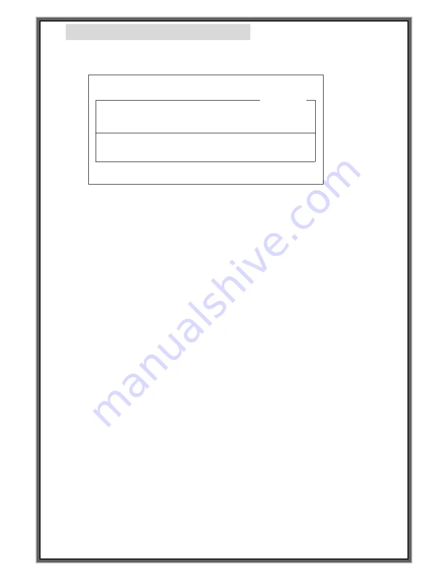
Below screen is indicated if press F3 on the keyboard.
3.
Check the location of cursor. Can move the cursor if press ENTER key on the keyboard.
4.
Can move the block no. through arrow key(↓ , ↑) on the keyboard in case of single block.
Can move first 2 block no. through PgDn, PgUp on the keyboard and last 2 block no. through arrow key
In case of multi block. Ex.: [00.00]
*In case of single block, block no. is indicated BLK NO.[000],
In case of Multi block, block no. is indicated BLK NO.[00.00].*
5.
In case indicating the < NO BLOCK DATA > on the BLK NO[001] same as above pictures,
press
“
SPACE BAR
”
on the keyboard to activate
6.
[EDIT CHA. Size] Press ENTER on the keyboard and input the value that you want. [Unit : 0.1 mm]
7.
[EDIT the distance between the center of each cha.] Press Enter on the keyboard and
input the value that you want [Unit : 0.1 mm]
8.
[EDIT the marking location] Press Enter on the Keyboard and input the value of X:0000 and Y:0000
9.
[SELECT FONT] Press Enter on the Keyboard and then move to FNT:STD1.
Press SPACE BAR to change the FONT
FONTS are changed as following whenever press SPACE BAR STD1 -> STD2 -> DOT -> USER1 -> USER2
-> USER3 -> USER4
10.
[EDIT Serial no.]Press Enter on the keyboard to move L:00000000.
And then input the serial number.
11.
[EDIT Marking DATA] Press Enter on the Keyboard to move <DATA> on the screen.
Then type the marking data.
12.
Press F2 if the change has been completed all.
**On RS-232 communication mode, set the controller at [F8] Communication mode**
F1 : M_MENU F2 : A_MARK F3 : EDIT F4 : FILE
F5 : SETUP F6 : TEST F7 : LOAD F8 : COMM
BLK NO. [ 000 ]
LN X : 0300 Y : 0300 A : 000
FNT : STD1 CH:030 PX:030 L:00000000 I:+1
<DATA> PAUSE : N
JEIL MTECH
[EDIT MODE]
BLK_COPY : CTRL_C BLK_MOVE : UP/DOWN
CURSOR_MOVE : ENTER SELECT : SPACE_BAR
BLK NO. [ 001 ]
EMT
< NO BLOCK DATA >
Summary of Contents for MCU-100N
Page 8: ...8 F1 MANUAL MARK MODE...
Page 10: ...10 F2 AUTO MARK MODE...
Page 35: ...35 F4 DATA MODE...
Page 39: ...39 F5 SETUP MODE...
Page 47: ...47 F6 TEST MODE...
Page 49: ...49 F7 FILE LODE MODE...
Page 52: ...52 F8 COMMUNICATION MODE...
Page 59: ...59 How to Create PLT file by standard AUTO CAD 2006...
Page 73: ...73...
Page 79: ...79...
Page 80: ...80...
Page 94: ...94 How to Modify the data of block and modify the time of the controller...


