


1-Jul-2017
Page 59
001223MAN-05
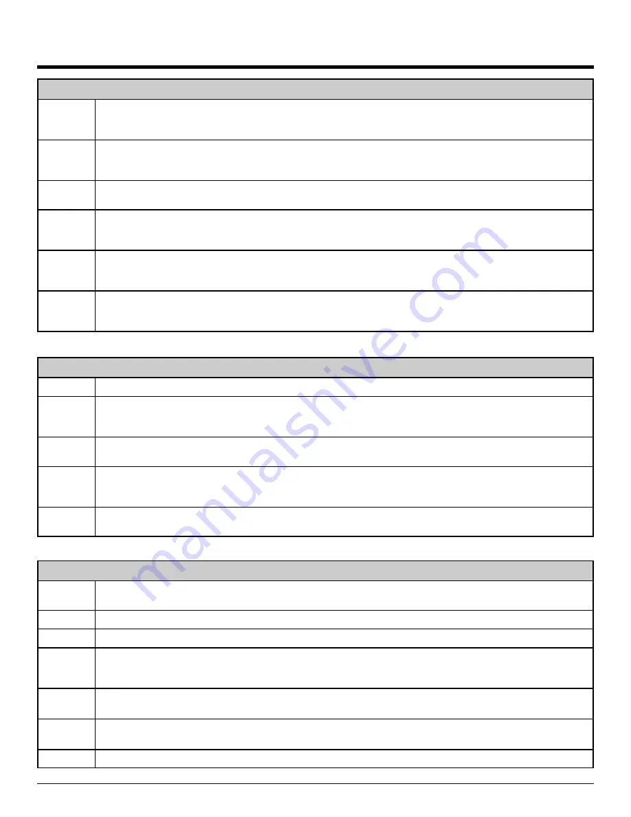
PUMP DOWN PROCEDURE
STEP 1
Connect the refrigerant recovery unit to the heat pump service ports via a refrigeration charging manifold
and to a recovery tank as per the instructions in the recovery unit manual.
If there was a compressor burn
out, the refrigerant cannot be reused and must be disposed of according to local codes.
STEP 2
All water coil heat exchangers must either have full flow or be completely drained of fluid before recovery
begins. Failure to do so can freeze and rupture the heat exchanger, voiding its warranty. Note that this
does not apply to double wall domestic hot water exchangers (desuperheater coils).
STEP 3
Ensure all hose connections are properly purged of air. Start the refrigerant recovery as per the instructions
in the recovery unit manual.
STEP 4
Allow the recovery unit suction pressure to reach a vacuum. Once achieved, close the charging manifold
valves. Shut down, purge and disconnect the recovery unit as per the instructions in its manual. Ensure the
recovery tank valve is closed before disconnecting the hose to it.
STEP 5
Connect a nitrogen tank to the charging manifold and add nitrogen to the heat pump until a positive pres-
sure of 5-10PSIG is reached. This prevents air from being sucked into the unit by the vacuum when the
hoses are disconnected.
STEP 6
The heat pump is now ready for repairs. Always ensure nitrogen is flowing through the system during any
brazing procedures to prevent oxidation inside the pipes. Maritime Geothermal Ltd. recommends replacing
the liquid line filter-dryer any time the refrigeration system has been exposed to the atmosphere.
VACUUM AND CHARGING PROCEDURE
STEP 1
After completion of repairs and nitrogen pressure testing, the refrigeration circuit is ready for vacuuming.
STEP 2
Release the refrigerant circuit pressure and connect the vacuum pump to the charging manifold. Start the
vacuum pump and open the charging manifold valves. Vacuum until the vacuum gauge remains at less
than 500 microns for at least 1 minute with the vacuum pump valve closed.
STEP 3
Close the charging manifold valves then shut off and disconnect the vacuum pump. Place a refrigerant tank
with the proper refrigerant on a scale and connect it to the charging manifold. Purge the hose to the tank.
STEP 4
Weigh in the appropriate amount of refrigerant through the low pressure (suction) service port. Refer to the
label on the unit or the
Refrigerant Charge Chart
in the
MODEL SPECIFIC INFORMATION
section for the
proper charge amount.
STEP 5
If the unit will not accept the entire charge, the remainder can be added through the low pressure service
port after the unit has been restarted.
REPLACEMENT PROCEDURE FOR A COMPRESSOR BURN-OUT
STEP 1
Pump down the unit as per the Pump Down Procedure above. Discard the refrigerant according to local
codes.
STEP 2
Replace the compressor. Replace the liquid line filter-dryer.
STEP 3
Vacuum the unit until it remains under 500 microns for several minutes with the vacuum pump valve closed.
STEP 4
Charge the unit with
NEW REFRIGERANT
and operate it for continuously for 2 hours. Pump down the unit
and replace the filter-dryer. Vacuum the unit until it remains under 500 microns for several minutes with the
vacuum pump valve closed.
STEP 5
Charge the unit (refrigerant can be re-used) and operate it for 2-3 days. Perform an acid test. If it fails,
pump down the unit and replace the filter-dryer.
STEP 6
Charge the unit (refrigerant can be re-used) and operate it for 2 weeks. Perform and acid test, If it fails
pump down the unit and replace the filter-dryer.
STEP 7
Charge the unit a final time. Unit should now be clean and repeated future burn-outs can be avoided.
Repair Procedures
Summary of Contents for TF-45
Page 12: ...Page 12 001223MAN 05 1 Jul 2017 ...
Page 13: ...1 Jul 2017 Page 13 001223MAN 05 ...
Page 14: ...Page 14 001223MAN 05 1 Jul 2017 ...
Page 15: ...1 Jul 2017 Page 15 001223MAN 05 ...
Page 16: ...Page 16 001223MAN 05 1 Jul 2017 ...
Page 19: ...1 Jul 2017 Page 19 001223MAN 05 ...
Page 20: ...Page 20 001223MAN 05 1 Jul 2017 ...
Page 23: ...1 Jul 2017 Page 23 001223MAN 05 ...
Page 24: ...Page 24 001223MAN 05 1 Jul 2017 ...
Page 25: ...1 Jul 2017 Page 25 001223MAN 05 ...
Page 26: ...Page 26 001223MAN 05 1 Jul 2017 ...
Page 27: ...1 Jul 2017 Page 27 001223MAN 05 ...
Page 30: ...Page 30 001223MAN 05 1 Jul 2017 ...
Page 31: ...1 Jul 2017 Page 31 001223MAN 05 ...
Page 32: ...Page 32 001223MAN 05 1 Jul 2017 ...
Page 33: ...1 Jul 2017 Page 33 001223MAN 05 ...
Page 34: ...Page 34 001223MAN 05 1 Jul 2017 ...
Page 38: ...Page 38 001223MAN 05 1 Jul 2017 ...
Page 39: ...1 Jul 2017 Page 39 001223MAN 05 ...
Page 40: ...Page 40 001223MAN 05 1 Jul 2017 ...
Page 74: ...Page 74 001223MAN 05 1 Jul 2017 Wiring Diagram 208 230 1 60 ...
Page 75: ...1 Jul 2017 Page 75 001223MAN 05 Electrical Box Layout 208 230 1 60 ...
Page 76: ...Page 76 001223MAN 05 1 Jul 2017 Wiring Diagram 208 3 60 ...
Page 77: ...1 Jul 2017 Page 77 001223MAN 05 Electrical Box Layout 208 3 60 ...
Page 78: ...Page 78 001223MAN 05 1 Jul 2017 Wiring Diagram 460 3 60 ...
Page 79: ...1 Jul 2017 Page 79 001223MAN 05 Electrical Box Layout 460 3 60 ...
Page 80: ...Page 80 001223MAN 05 1 Jul 2017 Wiring Diagram 220 1 50 ...
Page 81: ...1 Jul 2017 Page 81 001223MAN 05 Electrical Box Layout 220 1 50 ...
Page 82: ...Page 82 001223MAN 05 1 Jul 2017 ...
Page 83: ...1 Jul 2017 Page 83 001223MAN 05 ...
Page 84: ...Page 84 001223MAN 05 1 Jul 2017 ...
Page 85: ...1 Jul 2017 Page 85 001223MAN 05 Dimensions TF 45 Left Return ...
Page 86: ...Page 86 001223MAN 05 1 Jul 2017 Dimensions TF 45 Right Return ...
Page 87: ...1 Jul 2017 Page 87 001223MAN 05 Dimensions TF 55 65 75 80 Left Return ...
Page 88: ...Page 88 001223MAN 05 1 Jul 2017 Dimensions TF 55 65 75 80 Right Return ...


