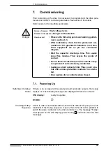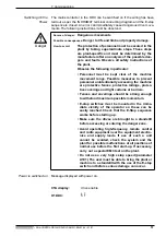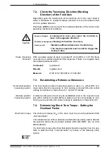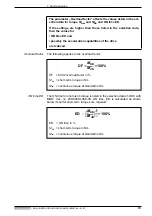
6. Parameter Input
• DOK-CONTRL-DDC+MDD+DLC-ANW1-EN-E1,44 • 01.97
51
6.7.
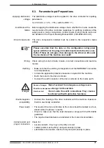
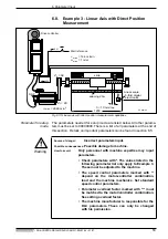
Example 2 - Linear Axis with Incremental Position
Measurement (e.g., motors with digital DSF
servo feedback)
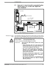
Fig 6.8: Linear axis with incremental position measurement
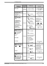
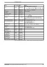
Parameter for setup
mode
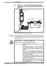
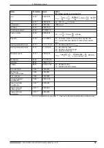
The parameters needed for setup mode are listed below. All other parame-
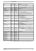
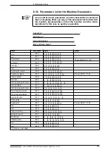
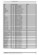
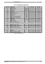
ters must be set to 00000000. There is a list of all parameters at the end of
this section. Details on important parameters can be found in section 6.5.
Warning
Drive controller
Start reference
DSF
Z
2
= 56
Z
1
= 35
1200
measured
position (600)
h = 10 mm/Umdr.
v
max
= 18 m/min
a
max
= 1 m/s
2
n
max
= 2880 min
-1
FPinkmes
E02
E01
slide
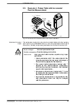
Source of danger:
Incorrect parameters input.
Possible consequences:
Possible damage to machine.
How to avoid:
Only personnel with machine expertise may input
parameters.
• Check parameters with *. The values listed in the
following parameter list only apply to Example 2.
These must be adjusted to the machine.
• The speed control parameters marked with **
depend on the motor-controller combination,
load and the machine mechanics. Set standard
speed control parameters.
• Parameter overload factor marked with *** must
be matched to the motor/controller combination.
See setting overload factor.
• The machine manufacturer is responsible for the
DLC parameters. These can only be changed
with his permission.

