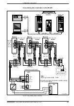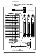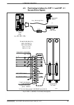
4. Electrical Connections
• DOK-CONTRL-DDC+MDD+DLC-ANW1-EN-E1,44 • 01.97
33
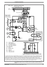
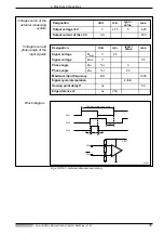
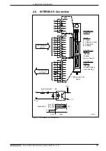
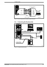
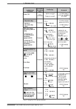
Fig 4.10: DEF - technical data and input wiring
360
°
electrically = one cycle
t2
t1
t1
U
a1
U
a0
U
a2
SVDEF
U
ax
U
ax
+5V
Voltage source of the
external measuring
system
Designation
Unit
min.
typic./
value
max.
Output v5 V
V
4.75
5
5.25
Output current of the +5 V
mA
250
Designation
Unit
min.
typic./
value
max.
Signal voltage
U
High
V
2.5
Signal voltage
U
Low
V
0.5
Phase angle
U
a1
°
el.
0
Phase angle
U
a2
°
el.
90
Maximum input frequency
kHz
1000
Signal cycle interpolation
4-fold
Homing point delay t1
ns
50
Edge distance t2
ns
250
Voltage level and
phase angle of the
input signals
Block diagram


