background image

6. Parameter Input     

 • DOK-CONTRL-DDC+MDD+DLC-ANW1-EN-E1,44 • 01.97

55

6.9.

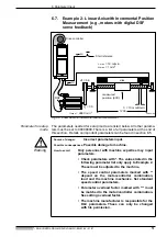
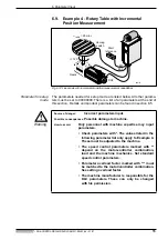
Example 4 - Rotary Table with Incremental 
Position Measurement

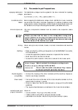
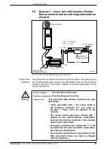
Fig 6.12: Linear axis with incremental position measurement capabilities

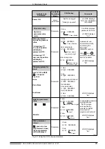
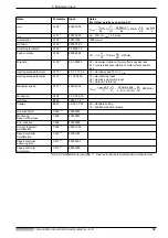
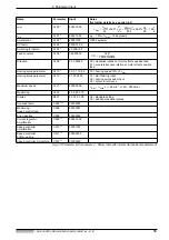
Parameter for setup

mode

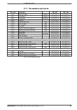
The parameters needed for setup mode are listed below. All other parame-
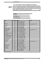
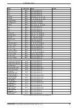
ters must be set to 00000000. There is a list of all parameters at the end of
this section.  Details on important parameters can be found in section 6.5.

Warning

PZDreh

DSF

Gears

A1

A2

i = 120

table

 = 25 min

-1

Homing

switch

E02

E01

Start

reference

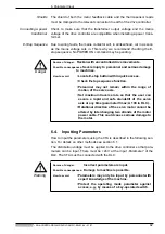
Source of danger:         

Incorrect parameters input.

Possible consequences:

 Possible damage to machine.

How to avoid:

Only personnel with machine expertise may input
parameters.

• Check parameters with *. The values listed in the

following parameter list only apply to Example 4.
These must be adjusted to the machine.

• The speed control parameters marked with **

depend on the motor-controller combination,
load and the machine mechanics. Set standard
speed control parameters.


• Parameter overload factor marked with *** must

be matched to the motor/controller combination.
See setting overload factor.

• The machine manufacturer is responsible for the

DLC parameters. These can only be changed
with his permission.

Summary of Contents for Indramat DDC 1

Page 1: ...DDC and MDD Digital Intelligent AC Servo Drives with Single Axis Positioning Module DOK CONTRL DDC MDD DLC ANW1 EN P Application Manual mannesmann Rexroth engineering Indramat 271433 ...

Page 2: ...ioning support through to setup operations to support the application of DLC functions to assist in locating and clearing faults Editing sequence Copyright INDRAMAT GmbH 1996 Copying this document and giving it to others and the use or communica tion of the contents thereof without express authority are forbidden Offen ders are liable for the payment of damages All rights are reserved in the event...

Page 3: ...ections of the DDC 19 3 3 DDC dimensional data 20 3 4 Frontal view DDC 1 21 3 5 Coupling the Feed Motor to the Machine 22 4 Electrical Connections 23 4 1 Terminal diagram DDC 1 1 25 4 2 Controlling the Mains Contactor 26 4 3 DLC 1 1 Single Axis Positioning Module 28 4 4 DEA 4 1 DEA 5 1 and DEA 6 1 Input Output Interfaces 30 4 5 Positioning Interface for DEF 1 1 and DEF 2 1 Square Wave Signals 32 4...

Page 4: ... Parameter Input Limits 59 7 Commissioning 60 7 1 Powering Up 60 7 2 Check the Traversing Direction Working Direction of the Feed Axis 62 7 3 Establishing a Reference Dimension 62 7 4 Determining Short Term Torque Setting the Overload Factor 62 7 5 Error Reaction 64 7 6 Check Motor Holding Brake 67 7 7 Parametrizing the Speed Controller 68 7 8 Check Drive Load 70 7 9 Securing Data 71 8 Functions o...

Page 5: ...ting Status Display of the Drive Controller 91 9 2 Fault Displays of the Drive Controller 92 9 3 Diagnostics Possibilities with a CTA Programming and Display Unit 101 9 4 Error Displays of a CTA Programming and Display Unit 102 9 5 Replacing the Battery 104 9 6 Replacing the Forward Feed Motor 105 9 7 Fault Report 108 10 Index 110 ...

Page 6: ...Table of Contents DOK CONTRL DDC MDD DLC ANW1 EN E1 44 01 97 6 ...

Page 7: ...ive with the DLC 1 1 single axis positioning module means that the drives can be operated as digital intelligent single axis posi tioning controllers Fig 1 1 Digital AC servo drives and single axis positioning modules DLC 1 1 M 3 Digital intelligent drive controller with single axis positioning module digital AC servo motor higher level system Posi tioning module DLC max 4 plug in modules Paramete...

Page 8: ...doc no 109 0852 4102 DLC1 A Single Axis Positioning Module for Drive Controllers Programming Guidelines 1 1 Types of Digital Drives Drive controllers for digital AC servo drives are available in the following hou sing designs modular housing compact housing protection categories IP10 and IP65 Drive controllers for modular housing A drive package is made up of one supply unit and several drive cont...

Page 9: ...The drive controllers with protection category IP 65 can be directly installed to the forward forward feed unit This means that motor power and feedback cables which are long and conducted through the entire facility thus making them susceptible to excessive faults are no longer needed The forward forward feed unit can be operated as a standalone unit It can also be tested independently of the mac...

Page 10: ...t be possible to functionally adjust the respective drive controller This is achieved by equipping the basic unit with different auxiliary plug in cards and a matching software module The thus equipped basic unit is designated a configured drive controller This configured drive controller together with a digital MDD AC servo motor creates a system configura tion Configured drive controller The con...

Page 11: ...ents the basic unit a DLC single axis positioning module the software module an optional auxiliary plug in module the configuration rating plate Fig 2 2 DDC1 configured drive controller A1 A2 Drive controller basic unit Software module DSM Auxiliary plug in module PZmodDDC Configuration rating plate DLC single axis positioning module Slot U5 Slot U4 Slot U3 Slot U2 Slot U1 DSM DLC ...

Page 12: ...ning module expands the drive controller to create a standalone single axis positioning controller This controller can be program med with up to 3 000 program blocks Each program block specifies one motion sequence or a specific state of the inputs that require monitoring or of the outputs that need to be set Fig 2 4 A front view of a DLC DC DC A B C K1 Motor feedback µP Bb1 ready to switch power ...

Page 13: ...ion Software modules can be duplicated for additional identical machines or to back up the parameters This is done over a serial interface Standard software module The drive specific parameters determined by INDRAMAT are stored in the feedback of the MDD motors and are activated during commissioning as needed The user specific parameters are set on site on the machine to the machine dependent valu...

Page 14: ...tion with the single axis positioning module DLC 2 1 The operating modes target position entry and local operations are possible In local operations it is pos sible to replace the physical I O level with the interbus S interface module Fig 2 6 Auxiliary plug in cards 2 5 Configuration Rating Plate The type designation is on the configuration rating plate the configured drive controller the basic u...

Page 15: ... case TSDDC SYSTEMCONFIGURATION DDC 1 1 K050A DL01 00 DDC 1 1 K050A A DSM 2 1 C11 01 RS DLC 1 1 DEA 4 1 COVER COVER U 1 U 2 U 3 U 4 U 5 TYS DDC 1 1 W050A DL01 00 Slot designation Type of configured drive controllers Basic unit type Plug in module type Software module type Configuration rating plate type COVER cover no plug in module in slot Product name DDC Series 1 Version 1 Cooling liquid air co...

Page 16: ...F motors with digital servo feedback and multiturn encoders DSF MTG Fig 2 10 Feedback features Digital Feedback Sensor Principle optical probing of code disc Position resolution achieved 256 x 213 2 097 152 increments revolutions System accuracy 0 5 angular minutes Multiturn type 4 095 99 rotor revolutions Available with MDD 065 through MDD 115 Suitable applications high demands made of control dy...

Page 17: ...ded 1 Name 2 Motor size 3 Motor length 4 Housing type 5 Rated speed 6 Balance class 7 Side B shaft end 8 Motor feedback RSF RSF IDG DSF DSF MTG G K L M 9 Centering diameter 10 Output shaft 11 Power conn mounting orientation 12 Blocking brake without blocking brake with blocking brake 14 0 Nm with blocking brake 40 0 Nm with blocking brake 60 0 Nm 0 1 2 3 Example MDD 112 B N 015 N 2 L 130 G B 0 TLM...

Page 18: ...r parts that could be affected by this hot air stream e g PVC cable ducts should maintain a minimum distance of 300 mm to the air out let Fig 3 1 DDC with air inlet and outlet and position of the bleeder resistor The DDC 1 1 generally requires no maintenace If it is operated in a highly polluted environment and the blower mesh and heatsinks are at risk of becoming excessively dirty e g with foundr...

Page 19: ...C Make sure that these are properly installed so that the IP65 protection category of the DDC is in not negatively affected Fig 3 2 Installing cable leadthroughs 1 Release screw 1 2 Open cover shroud 2 3 Release knurled screw 3 4 Pull sheet metal cover off 4 5 Remove gasket 5 6 Place cable in the gasket 5 7 Following instructions in reverse order 8 Screw 1 tightly into place until cable leadthroug...

Page 20: ...e shroud air inlet 25 22 5 140 space for cable 775 with blower 470 635 without blower air inlet 145 65 40 Protective shroud 7 air outlet 165 165 9 5 7 13 140 7 5 10 500 517 5 without blower 657 5 with blower 298 220 275 MBDDC Motor power connection Mains conn Interface to machine controller Interface to machine controller 110 27 5 160 45 ...

Page 21: ...ion X4 RS 232 interface connection for VT 100 terminal or PC X2 Status display warning and error signals H1 Fault reset key S1 Slot for software module U5 Additional slots U2 U3 U4 for auxiliary plug in modules Motor power connection Analogue inputs and outputs X3 Configuration rating plate Interface to machine controller Cable leadthrough Blower connector SYSTEMKONFIGURATION Basic unit rating pla...

Page 22: ...g coupling The axial compensation must be able to pick up the axial displacement which results from the expansion due to heat of motor and recirculating ball screw or even from the axial motions of machine com ponents Without sufficient axial compensation it is possible to damage the axial bearing in the feed motor Gear coupling Only gears with straight teeth should be used to avoid axial forces o...

Page 23: ...ection category IP 65 can be directly installed on the for ward feed unit This means that long interference susceptible connections between the forward feed unit and the control enclosure have been reduced to a minimum The single axis positioning module is integrated in the drive There is no need for a corresponding connection in the machine Fig 4 1 Examples of station connections DDC PZstatio A1 ...

Page 24: ...one sided over the greatest possible surface area on the unit side of the chassis housing With digital signals it is advisable to lay the shield on both ends of the cable over the greatest surface possible on the chassis housing Signal and control leads must be routed at least 10 cm away from power cables Routing in separate cable ducts is the best solution Signal and control leads should only cro...

Page 25: ... SCL FS X4 C C S S 0VM UG IN 290 optional interface U2 optional interface U3 optional interface U4 DSM programming module U5 Analogue diagnostics outputs AK1 0VM AK2 0VM IN 172 IN 108 with DDC 1 1 K050B TxD RxD RTS CTS 10 5 4 3 2 1 CTS RTS RxD TxD 0VM RS 232 interface X2 PE 1 2 3 L1 N HW M X9 D C B A 10 6 5 1 8 12 3 2 4 7 9 WH 12 GN BN PK RG BN 12 BK RD BL VI 1 heatsink blower 4 3 2 1 X3 26 25 24 ...

Page 26: ...relay opens then K3 and K4 safely switch the mains con tact K1 off At the same time the machine control switches the drive enable signal RF input with analog interface E stop input of the DEA 4 if the sin gle axis positioning module DLC is used This brings about drive internally a command value to zero of the drive The drive is brought to a controlled stop A drive error signal from the Bb contact ...

Page 27: ... ready signal S1 S4 Control voltage S11 S12 S5 K1 E stop relay K10 safety doors closed Example Depending upon the safety requirements at the machine additional monitoring and locking measures may need to be taken E stop input DLC X8 9 X8 10 24 V Machine controller Machine E Stop UD 1 If the controller of the machine switches the E stop input of the DLC off while the UD contact is open then the mes...

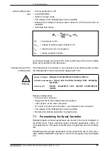
Page 28: ...C 1 1 terminal connecting plan APDLC Looking onto front panel DLC 1 1 X 31 X 30 X30 Rx TxD Rx TxD GND CTS RTS TxD RxD X31 Programming and display unit Ready made cable IKS 745 RS 232 RS 485 300R 1 2 3 7 8 5 4 6 34 33 32 2 1 1 2 3 7 8 5 4 6 34 33 32 2 1 9 pin D SUB connector IN 525 Part no 259 759 CR 7 4 5 6 1 2 3 8 9 0 3 CL ...

Page 29: ...2 RS 485 RS 485 RS 485 RS 232 PC SOT Drive controllers X31 X31 X31 DLC 1 1 Station No 1 DLC 1 1 DLC 1 1 X2 SOT External user terminal RS232 RS485 connector housing 4 1 24V 0V X1 24V 0V Station No n Station No 32 D Sub 9 pin Schirm GND Rx Tx Rx Tx D Sub 9 pin D Sub 9 pin D Sub 9 pin only with DLC with plastic front panel End plug GND Rx Tx Rx Tx Shield Matching resistor 300R 470R Do not route data ...

Page 30: ...1 OUT 12 OUT 13 OUT 14 OUT 15 DEA 5 1 X 32 DEA 6 1 X 33 BKGN GYPK RDGN BKYE GNBU RDBU BNYE BNGY RDWH WHPK BKWH BNPK YEWH GNWH BUWH GNGY GYWH WH VT YE PK BU YEGY GNPK YEPK BNBU BNGN YEBU RDYE BNRD BKBN BN BK GY 0 5 mm2 RD GN 0 5 mm2 GNYE 05 mm2 DC 0 Vext ERR ERR ERR Parameter Automatic Setup E Stop Start Immed Stop Jogging forwards Jogging backwards Clear E 01 E 02 E 03 E 04 E 05 E 06 E 07 Error Se...

Page 31: ...locked until the supply voltage has been switched on and off once in rapid sequence If driver UDN 2987 A has switched off one or several outputs because of overload then the error will be displayed by the switched on LED Notes on LED ERR Designation Unit min typical max Supply voltage Uext V 18 24 32 Current consumption Iext A 0 15 0 2 1 2 2 2 Inputs X17 1 15 UHigh V 14 24 32 ULow V 0 1 3 Outputs ...

Page 32: ...bminiature connector IN 439 mounted with screws part no 252 884 X22 X24 Ua0 Ua1 Ua1 8 1 3 4 5 6 7 2 9 10 11 12 13 14 15 Ua2 Ua2 Ua0 Ua0 Ua1 Ua1 Looking towards front panel 8 1 3 4 5 6 7 2 9 10 11 12 13 14 15 1 1 The color coding applies to INDRAMAT cables IN 209 X22 DEF 1 1 X24 DEF 2 1 Connector allocation of the postion interfaces for square wave signals DEF 1 1 X 22 DEF 2 1 X 24 Digital Drive e ...

Page 33: ...ystem Designation Unit min typic value max Output voltage 5 V V 4 75 5 5 25 Output current of the 5 V mA 250 Designation Unit min typic value max Signal voltage UHigh V 2 5 Signal voltage ULow V 0 5 Phase angle Ua1 el 0 Phase angle Ua2 el 90 Maximum input frequency kHz 1000 Signal cycle interpolation 4 fold Homing point delay t1 ns 50 Edge distance t2 ns 250 Voltage level and phase angle of the in...

Page 34: ...tor INTERBUS S Output RS 485 D subminiature 9 pin bushing 0 Vext 3K X39 2 5 0 VTTL X39 1 Signal level 15 V 0 low 1 high 3 V 10 max 32 V typic 24 V min 18 V Input circuits E1 E4 X39 DO 2 DI 2 GND 2 free 5 V 2 DO 2 DI 2 free RBST X41 INTERBUS S continued 1 2 3 4 5 6 7 8 9 1 2 3 4 5 DBS 2 2 X41 X40 H1 H2 A B C D 1 2 3 4 5 6 7 8 9 DO 1 DI 1 GND 1 free free DO 1 DI 1 free free X40 INTERBUS S coming 1 2...

Page 35: ... 5 6 7 8 9 DBS 2 X DO 2 DI 2 GND 2 free 5 V 2 DO 2 DI 2 free RBST X41 DO 1 DI 1 GND 1 free free DO 1 DI 1 free free X40 1 2 3 4 5 6 7 8 9 1 2 3 4 5 6 7 8 9 1 2 3 4 5 6 7 8 9 DBS 2 X DO DI GND 1 free 5 V DO DI free RBST 1 2 3 4 5 6 7 8 9 1 2 3 4 5 6 7 8 9 Master connection INTERBUS S continued H1 X4 X2 X5 X6 X9 X8 S1 X7 X3 SYSTEMKONFIGURATION APnetzDBS Interconnecting with INTERBUS S Master connect...

Page 36: ...emulates a VT 100 terminal This software is nee ded to visualize the user interface stored in the drive controller on the moni tor of the PC Service Cable IN 391 With the use of service cable IN 391 it is possible to connect a PC or a VT 100 terminal to the drive controller via connector X2 Do not connect either the PC or the VT 100 terminal to the drive controller while they are carrying current ...

Page 37: ... 5 2 Interface ISB 3 switch box Motion Manager The Motion Manager is an editor and communications program for writing and transmitting CLC user programs It facilitates DLC programming The Motion Manager can run on IBMcompatible computers PC Minimum requirements made of the PC MS DOS RS 232 interface drisk drive INDRAMAT Cable IKS 046 It is possible to connect a PC to the RS 232 interface of the DL...

Page 38: ...ature bushing serial interface V24 RS 232C DDC 1 1 IKS046 max 15 m long SBSerDDC TxD RxD RTS CTS SGND DTR DSR 3 2 7 8 5 4 6 SYSTEMKONFIGURATION RxD TxD SGND 2 3 5 X 31 APisb3 Interface switch box ISB 3 ISB 3 7 7 9 8 4 5 6 1 2 3 0 CL CR CLM X8 SYSTEMKONFIGURATION PC IN 391 optional X2 Multimeter Oscilloscope optional X3 X17 X30 IKS 138 must be ordered separately of ISB 3 X1 X2 X16 optional delivere...

Page 39: ... as needed with the CTA programming display unit The parameters are stored on the DLC card which is backed up by a lithium battery with a lifespan of approxi mately ten years Parameter Input The user interface of the programs Motion Manager and DDS2PC make it easy to input all parameters How to handle the programming and CTA display unit when inputting para meters is described in the following sec...

Page 40: ...in program or parameter block Key for clearing errors With this key the cursor is placed on defined input positions not effectual in parameter mode Cursor right cursor left 1 From the basic position of the cursor these keys are used to switch from one display to the other 2 These keys are used to call up commands in programm input mode The cursor must be placed at position behind the command 3 In ...

Page 41: ...oller Connect the earth conductor of the drive controller to the mains earth Danger Electromagnetic compatibility Connect the housing of the drive controller with the machine chassis so that it is electrically conductive Power leads The leads of the drive controllers to the motor should be twisted or a four strand cable 3x phase 1x earth Check to make sure that the lead diameters comply with the E...

Page 42: ...e drive controller so that para meters can be input There must be 24V at the input Parameter of the DLC The CTA must be connected with the DLC Warning Source of danger Reckon with uncontrolled drive movements Possible consequences Severe injury to personnel and serious damage to machines How to avoid Locate E stop button within quick access Check E stop sequence function Personnel may not remain w...

Page 43: ...00 Changing parameter block from A1 00 to B0 00 hit spacer key once twice three times four times V max A 1 00 00000000 Free B 0 00 00000000 Parameter A parameter can be selected directly by entering the three digit parameter number Using and scrolling in parameter block is possible H1 DDC displays bb Parameter H1 DDC displays bb Analog output channel 1 C 0 00 00000000 Set standard drive parameter ...

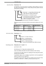
Page 44: ... 000300 00 Setup speed Parameter A 1 0 1 Input range 0 10 50 000 00 Decimal places 2 or 3 depending on parameter B 007 Speed in setup mode if system operation jogging forward or backward is set to logical 1 A 101 A 100 Caution Acceleration Parameter A 1 0 2 Input range 1 9999 9999 Decimal places 0 or 1 depending on parameter B 007 Check whether the acceleration programmed here is acceptable to the...

Page 45: ...ing the optimum value Feed Constant Parameter A 1 0 8 Input range 0 1000 5000 0000 or 0 01000 500 00000 Decimal places 4 or 5 depending on parameter B 007 That path is set here which results from one rotation of the position encoder It can be input in any unit of measurement e g mm cm inch degrees and so on The unit set here is designated the input unit EGE All other units must relate to this one ...

Page 46: ... message In automatic mode an error message is generated once the programmed position exceeds the travel range limit The position of the travel range limit as it relates to the zero point of the machine is not affected i e shifted by offset programming A 111 Parameter A 1 0 9 Parameter A 1 1 0 Rotational direction 0 0 0 0 0 0 0 0 0 0 0 0 0 0 0 0 0 0 forwards 0 1 backwards right left 0 1 0 0 0 0 0 ...

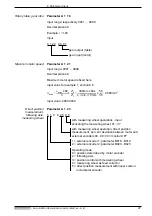
Page 47: ...2 0 0 0 0 1 gear output table gear input motor nmax vmax 60 h Z 2 Z 1 300mm 60s s min 10mm 56 35 2880min 1 5 1 0 0 2 0 0 0 with measuring wheel operations input activating the measuring wheel 01 37 with measuring wheel operation direct position measurement per cent deviation between motor and external encoders 00 99 00 monitor OFF 1 external encoder 1 parameter B016 B019 2 external encoder 2 param...

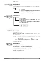
Page 48: ...r external position measurement Parameter B 0 1 8 Input range 0 1 5000 0000 Decimal places 4 or 5 depending on parameter B 007 Path per revolution of the external position encoder or with linear scale tra versing path for the number of pulses as per B 017 Example feed constant 5 mm Input value 0005 0000 0 0 0 2 0 0 0 0 02 standard 03 additional decimal places for an even finer resolution 00 German...

Page 49: ...0 measured position 600 h 10 mm rev v max 18 m min a max 1 m s2 n max 2880 min 1 FPabsmes Source of danger Incorrect parameters input Possible consequences Possible damage to machine How to avoid Only personnel with machine expertise may input parameters Check parameters with The values listed in the following parameter list only apply to Example 1 These must be adjusted to the machine The speed c...

Page 50: ...0 0 2 00 0 0 Travel range minimum A113 000000 00 Travel range maximum A114 000100 00 Maximum speed A121 2880 0000 Monitoring A122 0 0 00 0 010 Interface B003 0960 0 1 8 1 Display B007 00 02 0 0 00 02 standard setting 03 additional decimal places Overload factor C002 00000200 Monitoring Speed control loop C005 00000001 Absolute encoder Monitoring window C006 0000 5000 Absolute encoder Homing positi...

Page 51: ... h 10 mm Umdr v max 18 m min a max 1 m s2 n max 2880 min 1 FPinkmes E02 E01 slide Source of danger Incorrect parameters input Possible consequences Possible damage to machine How to avoid Only personnel with machine expertise may input parameters Check parameters with The values listed in the following parameter list only apply to Example 2 These must be adjusted to the machine The speed control p...

Page 52: ...arameter A110 0 0 0 1 10 0 0 10 Homing speed 10 of vmax Homing setup parameter A112 01 02 00 03 01 start homing input 02 Homing point switch input 03 Output in reference Maximum speed A121 2880 0000 Monitoring A122 0 0 00 0 010 Interface B003 0960 0 1 8 1 Display B007 00 02 0 0 00 02 standard setting 03 additional decimal places Overload factor C002 00000200 Monitoring Speed control loop C005 0000...

Page 53: ... 1 FPdirmes E02 E01 spacing 20µ Linear scale 5 fold digital electronics slide Source of danger Incorrect parameters input Possible consequences Possible damage to machine How to avoid Only personnel with machine expertise may input parameters Check parameters with The values listed in the following parameter list only apply to Example 3 These must be adjusted to the machine The speed control param...

Page 54: ...5 1 0 0 20 00 51 external encoder 1 mit DEF 1 1 20 permissible deviation in between motor and exter nal encoders Display B007 00 02 0 0 00 02 standard setting 03 additional decimal places external encoder 1 B016 1 0 0 00000 100 working direction of motor and external encoder same 101 working direction of motor and external encoder not the same external encoder 1 pulse B017 000 01250 external encod...

Page 55: ...switch E02 E01 Start reference Source of danger Incorrect parameters input Possible consequences Possible damage to machine How to avoid Only personnel with machine expertise may input parameters Check parameters with The values listed in the following parameter list only apply to Example 4 These must be adjusted to the machine The speed control parameters marked with depend on the motor controlle...

Page 56: ... effects positive feed Homing setup parameter A110 0 0 0 1 10 0 2 10 homing speed 10 of vmax Homing setup parameter A112 01 02 00 03 01 start homing input 02 homing point switch input 03 output in reference Maximum speed A121 3000 0000 Monitoring A122 0 0 00 0 010 Display B007 00 03 0 0 00 02 standard setting 03 additional decimal places Overload factor C002 00000200 Monitoring Speed control loop ...

Page 57: ... free A105 s a a a a a a a Switching threshold A106 s a a a a a a a a Preliminary signal A107 s a a a a a a a a a a only if B007 0 03 Feed constant A108 s a a a a a a a a Direction A109 s a a a a a a a Homing setup parameter A110 s a a a a a a a Homing offset A111 s a a a a a a a a Homing setup parameter A112 s a a a a a a a Travel range minimum A113 s a a a a a a a a a Travel range maximum A114 s...

Page 58: ... a a a a a a Ext enc 1 offset B019 s a a a a a a a external encoder 2 B020 s a a a a a a a Ext enc 2 pulse B021 s a a a a a a a Ext enc 2 VK B022 s a a a a a a a a Ext enc 2 Offset B023 s a a a a a a a Analog output channel 1 C000 s a a a a a a a Analog output channel 2 C001 s a a a a a a a Overload factor C002 s a a a a a a a Scaling position data C003 s a a a a a a a a Scaling speed data C004 s ...

Page 59: ...it EGE 0 0 0 0 0 0 0 0 9 9 9 9 9 9 9 9 A114 Maximum traversing range limit EGE 0 0 0 0 0 0 0 0 9 9 9 9 9 9 9 9 A116 Rotary table 0 0 0 0 0 0 0 1 0 0 0 0 9 9 9 9 A117 Break point EGE sec2 0 0 0 0 0 0 0 1 0 0 9 9 9 9 9 9 A121 Drive sensitivity 0 0 0 1 0 0 0 0 9 9 9 9 0 0 0 0 A122 Position monitoring window 0 0 0 0 0 0 0 1 0 0 0 0 0 1 0 0 B017 external encoder 1 pulse 0 0 0 0 0 1 0 0 0 0 0 2 0 0 0 0 ...

Page 60: ...s open then it should not be possible to switch the power contactor in the drive controller on The message E stop must appear on the CTA display press the key of CTA to clear the fault message Source of danger High voltage levels Possible consequences Danger to life and limb How to avoid Observe the following points and warning guideli nes in section 6 3 After installation check that the permanent...

Page 61: ...ust be kept clear of the machine movement range Possible measures to prevent personnel unintentionally accessing the machine are protective fences protective railings protec tive coverings and light curtains or barriers Fences and coverings should be strong enough to withstand maximum possible momentum E stop switches must be mounted in the imme diate vicinity of the operator so these can be easil...

Page 62: ... homing cycle each time the control voltage is swtiched on See setions 8 1 and 8 2 for details Absolute position measuring system A reference dimension must only be established once in the case where an axis with a multiturn encoder MTG is started up It is not necessary to run a homing cycle each time the control voltage is switched on See section 8 3 7 4 Determining Short Term Torque Setting the ...

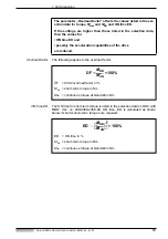
Page 63: ... are required The parameter Overload factor affects the values listed in the sel ection data for torque Mmax and MKB and ON time ED If the settings are higher than those listed in the selection data then the values for ON time ED and possibly the acceleration capabilities of the drive are reduced ÜF MKB MdN 100 ÜF C002 overload factor in MKB short term torque in Nm MdN continuous torque at standst...

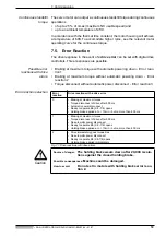
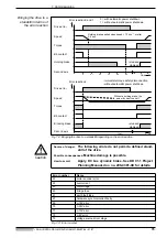
Page 64: ...ring down Error reaction 2 Torque disconnect without automatic power disconnect Error reaction 3 Error reaction selection Fig 7 1 Drive reactions with drive errors Caution Error reaction Drive reaction with a drive error 0 Braking at maximum torque Torque disconnect of drive after 500 ms Automatic power disconnect Ready to operate Bb X8 7 8 opens Holding brake applied at n 10min 1 but no more than...

Page 65: ...1 0 1 0 1 0 Without a holding brake the axis will coast to a halt Bb contact 1 0 1 0 released clamped Error reaction 2 immediate torque safety disconnection without automatic power shutdown Holding brake applied when speed 10 min 1 or after 0 4 sec Source of danger The following errors do not permit a defined stand still of the drive Possible consequences Machine damage is possible How to avoid Ap...

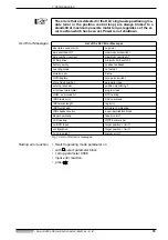
Page 66: ...C Error Messages absolute encoder error no power axis switched off 1 maximum limit switch 1 axis number incorrect maximum override A1 W Dog drive minimum limit switch 1 battery empty positive feedback operting mode not setup 1 division error E stop DPR illegible zero point switch 1 store block number parameter loss external encoder position monitoring 1 error input parameter program loss HOM comma...

Page 67: ...sed by slumping feed axes How to avoid Use INDRAMAT drive controllers only to control the motor holding brake When projecting the machine make sure that the braking time of the drive does not exceed 0 4 seconds Use a service brake for longer braking periods Do not set error reaction 2 in motors with holding brakes FPDDChb Error Internal speed command value to zero Motor torque Holding brake Time a...

Page 68: ... 0 V at pin G of the motor connector use separate motor connector The release of the holding brake must be audible Reclamp the holding brake after moving the axis 7 7 Parametrizing the Speed Controller Standard speed controller parameters are stored in the motor feedback of the MDD motor These standard speed controller parameters suffice for most applications The speed controller does not generall...

Page 69: ...ler Parameters Fig 7 6 Overview of speed controller parameters Fig 7 7 Speed controller terminal diagram Source of danger Incorrectly matched speed controller parameters affect the mechanical system of the machine Possible consequences Poor results reduced service life of the machine and possible damage to the machine How to avoid Speed controller parameters may only be set by qualified personnel ...

Page 70: ...mmed Load torque can be calculated using the motor current Load torque at feed velocity Do not exceed 60 of the continuous torque of the motor during standstill and at maximum feed velocity Causes of excessive load torque axis clamp has not been released insufficient lubricant blocking brake not released check connection weight counterbalance not sufficient recirculating ball screw sluggish too mu...

Page 71: ... number of delays Bleeder overload shut down may not occur If the bleeder prewarning contact opens or the mes sage bleeder overtemperature warning error 52 is signalled then approximately 75 of the continuous regenerative power is achieved 7 9 Securing Data On disk or harddrive With the editor and comminications program Motion Manager it is possible to easily store parameters and program on either...

Page 72: ...oltage is switched on Referencing prerequisites The safety limit switch must be in the E stop sequence Reference switch connected to DEA 4 and checked Parameters A 110 and A 112 programmed No interference contour workpiece between current position and refe rence switch Conduct drive start up as outlined in section 7 Fig 8 1 Referencing prerequisites Start referencing Reference cam Safety cam Homin...

Page 73: ... for the reference marker once the reference marker has been overshot Source of danger The axis can move in the wrong direction during referencing Possible consequences Personnel could be injured and machine damage is possible How to avoid Personnel may not remain within the danger zone of the machine There must be sufficient distance to the dead stop The machine operator must be readily able to a...

Page 74: ...tion masuring system to the DEF and check it Parameters must be programmed as per Section 6 No interference contour workpiece between current position and refe rence switch Conduct drive start up as outlined in section 7 FPabldiag Start homing cycle Axis running in direction of reference switch Axis holds for max one revolution after homing switch Absolute position shown in display Axis home yes y...

Page 75: ...tart referencing Reference cam Safety cam Reference switch Safety limit switch 24 V Message in reference Input 01 07 Input 01 07 Output 01 11 DEA 4 1 Digital electronics DEF 1 1 DSF FPvorrefer Slide Connected to drive and tested E stop sequence Drive controller Source of danger The axis can move in the wrong direction when homing Possible consequences Personnel could be injured and machine damage ...

Page 76: ...DEF 1 1 of fE 1 MHz equals the distance from in µm XL equals an angle of XL in µm resolution in µm 4 XD in resolution in 4 Note the mechanically permissing traversing range or the speed of the encoder e g DDS 2 1 DL05 00 XD in speed in U min resolution in 2000 4000 signal duration XL in µm 100 200 300 1 2 3 4 5 resolution in µm 0 25 0 5 0 75 1 6000 5000 7000 0 01 0 02 0 03 0 04 0 05 signal duratio...

Page 77: ...ol voltage is switched on Function principle Rotor position is detected cyclically and absolute and then processed in the drive controller with high resolution Within one motor revolution there is a resolution of 4096 positions The multiturn encoder makes absolute actual position detection over 4096 motor revolutions possible Prerequities for setting the reference dimension Saftey limit switch swi...

Page 78: ...working range with absolute indirect actual position evaluation at the motor equals 4096 revolutions FPfahrbe 2 3 3 3 Maximum braking path in motor revolutions 0 4096 Source of danger If the maximum working range is exceeded then the absolute reference dimension is lost Possible consequences Damage to the machine can result How to avoid Program parameter A 113 and A 114 travel range minimum maximu...

Page 79: ... 109 reads 0 1 000 000 Feed constant 6 25 mm Input value 4000 0000 hit switch operating mode off hit until the position appears in the CTA display The measured position is displayed e g 000600 00 Absolute encoder activate monitor The current actual position is stored in the drive controller once control voltage is off Stored position and actual position are compared once it is switched back on The...

Page 80: ...en the machine zero point and the reference point Caution working range min MZrefpu working range max Reference point Machine zero point s s a a a a a a a Offset in input units 2 or 3 decimal places depen ding on parameter B 007 0 machine zero point in a positive direction from the reference point 1 machine zero point in a negative direction from the reference point If the drive is equipped with a...

Page 81: ...ng range A 113 A 111 A 114 A 111 if zero point is moved in a negative direction if zero point is moved in a positive direction 8 5 Positioning Against a Dead Stop With the DLC single axis positioning module it is possible to run forward feed units in a controlled manner against a dead stop To do so it is neces sary to program a torque limit and a corresponding positioning command in the user progr...

Page 82: ...is switching to the next program block It is possible to branch to an error routine in the program program block no command input E 150 MOM 1 060 020 00 400 axis 1 constant torque limit 400 max drive torque input to activate constant torque limit 00 constant torque limit always active torque limit at the dead stop with PFI and PFA command Input range 0 100 100 25 of maximum drive tor que Torque li...

Page 83: ...0120 02 1 0106 JMP 105 0120 PSA 1 000000 00 999 0121 JST 0100 0200 AEA 07 1 0201 PSA 1 000000 00 999 0202 JST 0000 torque limit 60 to dead stop 20 at dead stop start run with 30 of vmax speed at 400 reduce to 10 run against dead stop to Pos 510 with v 10 jump to error routine jump to block 0120 if inut 02 is set work completed loop return to Pos 0 with maximum speed jump to stop after block 0100 w...

Page 84: ... in progress is not interrupted do not pro gram feed in the interrupt program 1 Feed in progress is interrupted Interrupt in subprogram 0 subprogram not interrupted 1 subprogram interrupted A positive edge at this input 01 37 starts the interrupt program 00 interrupt function not active 1 There is no automatic return to the interrupted main program 2 The interrupt vector is only available in Task ...

Page 85: ...witch Table of values with Gray Code speed override Fig 8 15 Table of values with Gray Code speed override Speed reduction relates to the speed which has been programmed 6 0 0 0 0 0 0 0 0 5 binary code 6 Gray Code input 04 07 24 V Gray coded stage switch DEA 4 1 E04 E05 E06 E07 12 13 14 15 1 16 X17 FPgesw Drive controller Input Speed in 04 05 06 07 0 1 1 0 0 0 1 1 0 0 0 0 0 0 0 0 0 1 2 4 0 1 1 0 1...

Page 86: ...meter input are switched off Fig 8 16 Operating modes If there is no error pending and if the power source is switched on UD con tact then setup mode is possible DEA 4 inputs Operating mode Parameter X17 1 Automatic setup X17 2 1 0 Parameter input 0 1 Automatic 0 0 Setup program block no command input E 0180 VEO 1 3 0 999 0 axis 1 0 Override in of programmed speed 1 Override as of vmax A100 0 1 99...

Page 87: ...ogram Signal sequence If the output automatic operating mode of the DLC is set then the automa tic program can be started Fig 8 19 Signal sequence in automatic mode Signal Connection E stop input DEA 4 X17 3 1 Immediate stop input DEA 4 X17 4 1 UD contact X3 9 10 closed Fault signal DEA 4 X17 16 1 Parameter DEA 4 X17 1 0 Automatic DEA 4 X17 0 1 TBsignve Input signal Output signal Automatic Operati...

Page 88: ... The following program sequence is to be programmed Positioning to 300 in rapid traverse with feed speed to 360 dwell time of 1s return to 10 in rapid traverse Fig 8 20 A simple processing program INDRAMAT Programming Language Fig 8 21 Program DGprog rapid feed 360 feed dwell time 1 s 300 10 0 Command Comment E 000 JMP 0100 jump to block no 100 E 0100 POA 1 000360 00 999 run to 360 with 99 9 of ma...

Page 89: ...solute dimensional notation E 0101 G62 speed optimized block transitions E 0102 F 018000 00 rapid traverse speed 18 m min E 0103 G01 1 000300 00 99 position to 300 E 0104 F 002000 00 feed speed 2 m min E 0105 G01 1 000360 00 99 position to 360 E 0106 F 002000 00 target speed anticipated with G62 in 1st or 2nd block after the positioning block E 0107 G60 exact positioning on E 0108 G04 01 00 dwell ...

Page 90: ...on measurements faulty drive move ments can result either from a fault within the aforementioned equipment or incorrect adjustments of the individual components as they relate to each other For a quick localization of faults the single axis positioning module and the drive controller have been equipped with an extensive diagnostics system Danger Source of danger Increased risk of accidents in the ...

Page 91: ...ether for the first time Actions Press reset key S1 The standard speed controller parameters are now loaded into the drive controller out of the motor feedback bb Ready signal No error was detected during the intialization phase The drive is ready to switch power on Power contactor switched on Ab Drive ready The power contactor is switched on The DC bus voltage is built up AF Drive enable The cont...

Page 92: ...l Remedy 1 Machine blower break down 2 Blower mesh dirty 3 Heatsink dirty 19 Motor overtemperature shutdown The motor has overheated to an unacceptable level For 30 seconds warning 51 was generated The drive is brought to a standstill in terms of the error reaction selected Remedy 1 The motor was overloaded The effective torque which the motor required exceeded the permissible continuous torque at...

Page 93: ...andstill as per the error reaction set Remedy Fault in the power source Phase failure 33 External voltage supply fault Auxiliary plug in module e g DEA 4 with galvanically isolated inputs and outputs must be supplied with 24 V DC Remedy The external 24 V DC are lacking or outside of the tolerance 1 Check motor encoder cable 2 Replace motor feedback defective Source of danger Displacement of dimens...

Page 94: ...e available for approxi mately four more weeks This error is generated each time the supply voltage is switched on Caution 50 Drive overtemperature warning flashing The heatsink of the drive controller has reached maximum permissible tem perature The drive can still maintain the command value for another 30 seconds This means that it is possible to bring the axis via the control to a standstill ap...

Page 95: ...he power transistor bridge has exceeded twice the value of the peak current of the machine The drive was immediately switched torque free as a result Remedy 1 Short circuit in motor cable 2 Power section of the drive controller defective 3 Short circuit in motor 61 Short to ground earth connection The sum of the phase currents is monitored During normal operation the sum 0 The earth connection fus...

Page 96: ... 24 Volt supply Remedy External consumer has a short circuit drive controller defective 71 10 Volt error There is a problem in the voltage supply to the current sensors Remedy Defect in the drive controller 72 8 Volt error There is a problem in the voltage supply to the encoder system Remedy Short circuit in the motor encoder cable or in the external encoder cable 73 Voltage supply driver stage Th...

Page 97: ...has actuated Remedy 1 Feedback mechanically twisted or defective 2 Feedback lead incorrectly poled 3 Drive blocked 4 Drive accelerating to current limit 81 Program RAM defective The storage subassemblies are checked in the drive controller during drive initialization If an error occurs during the course of this check then this error message is generated Remedy Hardware fault in drive controller 1 ...

Page 98: ...r message can only occur during factory test runs 86 Error while writing to parameter memory Remedy The parameter memory in the programming module will not accept data 87 Parameter data invalid During the controller initialization phase one or more parameters in the soft ware module were found to be invalid Remedy 1 The software module has not been previously initialized 2 The operating software E...

Page 99: ...ftware and hardware configurations do not match 2 Plug in module defective not installed or not properly inserted 3 Break in feedback lead 92 Absolute encoder not calibrated Parameter homing position and or counting direction in the menu ABSO LUTE ENCODER PARAMETER could not be read Remedy 1 These parameters have not yet been entered 2 Feedback defective 1 Check motor feedback cable and replace if...

Page 100: ... drive controller s processors error no 93 will be generated in the DKS Remedy DLC card or drive controller defective 94 Unacceptable software combination The software for the drive controller in the DSM software module and in the single axis positioning module DLC do not match Remedy 1 Replace the DLC card If the error is still present after the DLC card has been replaced replace the drive contro...

Page 101: ...8 22 23 37 Outputs 01 16 17 32 33 48 49 64 65 80 81 96 system ready If cursor in line 1 block number 1 block number 1 1 1 System outputs 1 1 Option E A Erw m DEA5 DEA6 comm 0000 rpm act 0000 rpm Relative measurement Pos 000003 12 SF 000000 00 REST 000000 00 System inputs 11 1 1 123456 78 999 1 16 1 16 E Progr Status Task1 0000 NOP Drive diagnosis e g A 1010 counter in automatic mode Manual A1 Driv...

Page 102: ...ilure storage set no The previously programmed program set is faulty Check the respective program Failure external encoder Signals of the external path measuring systems are faulty Check encoder lead Lag between motor and external encoder DEF defective input error Parameter A100 The parameter indicated was incorrectly programmed Check parameters Failure HOM command A1 HOM command not possible Go t...

Page 103: ...am sets Replace battery at the DLC if necessary Failure RTS nesting A program is concluded with RTS which was not called up with JSR or it has been pro grammed with CST 0 Check program Failure SAC command SAC command was called up with a non setup axis Check program Reference axis Failure lag error 1 The drive cannot comply with the command value Reduce acceleration Check weighted torque Check whe...

Page 104: ...ge battery empty will appear on the CTA display each time the power supply is switched on Output fault NOT of the DLC remains at 0 If the error message is cancelled then it will still appear every ten minutes Output fault NOT remains at 1 The DLC can still function Replacing the battery With power off pull the DLC plug in module out of the drive controller Caution If the connections at connector X...

Page 105: ... 9 4 Zero point in motors with keyways Motors with relative position detection without keyway When replacing a motor the reference dimensions shift within one motor revolution This can cause damage to the workpiece the tool or the machine Gauging is therefore advisable each time a motor is replaced Gauging is simplest if the machine is marked at specific reference points i e the reference point is...

Page 106: ...icated in parameter return offset 0 Enter 0 if necessary Read rotor position and enter the current angle e g 215 0313 degrees as the reference offset Switch on setup mode at the DLC and reference the axis again The axis should be located at the marker Marking any point The position of the marker must be known A CTA programming and display unit must be connected to the drive controller It is now po...

Page 107: ...sition 402 43 A111 00100 00 400 402 43 A111 00102 43 Switch on setup mode and reference again Run the axis to the measured position The position in the CTA must agree with the command value position Motors with absolute position determination As a result of replacing a motor it is possible that the reference dimensions are inaccurate within the entire position detection range To reestablish this r...

Page 108: ...ns is temperature dependent unknown connection error external causes mechanical damage loose cable conn moisture in unit extrinsic object in unit problem in mech sys controller breakdown motor breakdown cable break blower defective feedback defective Is there an air conditioner in control enclosure Y N Have there been previous problems with this axis How often Have the problems always occurred on ...

Page 109: ...MAT GmbH Bgm Dr Nebel Straße 2 Dept QSP D 97816 Lohr am Main GERMANY S No _ _ _ _ _ _ _ _ _ _ _ A _ _ S _ _ Configuration rating plate Software module Plug in module Unit rating plate U5 U1 U2 U3 U4 Slot The function of digital drive controllers is determined by the configuration of software module and plug in modules Problems can be caused by faulty modules or unpermitted configurations The follo...

Page 110: ...r resistor 12 Brake error 96 Braking 12 C Cable IN 391 36 Check Drive Load 70 Check Motor Holding Brake 67 Check the Traversing Direction 62 CL key 92 CLEAR input 92 Commissioning 60 compact housing 8 Compatibility of sotware modules 13 Conditions at the Mains 41 Configuration error 99 Configuration Rating Plate 14 Configured drive controller 10 Connecting a power transformer 42 Contact points and...

Page 111: ...C Fehlermeldung 66 Drive Components 41 Drive enable 91 Drive halt 91 Drive ready 91 DSF servo feedback 51 Duplication 13 E Earthing 41 EGE 45 Ein Ausgangsinterface 14 Einachspositioniermodul 12 Ein Ausgangs interface 30 Einrichtbetrieb 60 Electrical Connections 23 Electromagnetic compatibility 41 Emulationssoftware 36 Error Displays 102 Establishing a Reference Dimension 62 E Stop Sequence 42 Exte...

Page 112: ...Interface Schaltbox 37 Interrupt Vector 83 ISB 3 37 K Keyboard Functions 40 Komponenten 10 KV Factor 45 L Lagemessung 51 Load torque at feed velocity 70 M Mains contactor control 27 Maximum Speed 44 Maximum traverse rate 76 Measuring wheel 47 Minimum Equipment 36 modular housing 8 Montage 18 Motion Manager 37 39 Motor encoder error 93 Multiturn Encoder 77 N Netzbedingungen 41 Not AUS Kette 60 O Of...

Page 113: ...ary Table 55 S Safety distances 18 Saftey limit switch 77 Securing Data 71 Servicekabel IN 391 36 Setup Mode 86 Setup mode parameter 49 Setup speed 44 Shields 42 Short to ground 95 Signal sequence 26 87 Smoothing time constant 70 Software Module 13 Speed Override 84 station connections 23 Stillstandsdauerdrehmoment 64 System configuration 10 Systemvorstellung 7 T Technical data 31 Terminal diagram...

Page 114: ...10 Index DOK CONTRL DDC MDD DLC ANW1 EN E1 44 01 97 114 Weight counterbalance 71 Wiring 41 Working direction 45 ...

Page 115: ...Indramat ...

Reviews: