


3-90
IT
EN
DE
IT
EN
DE
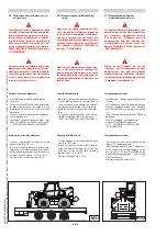
Dosing pump assembly positions
Always position the dosing pump with the
delivery side upwards.
Respect the minimum inclination of 15°!
Any assembly position exceeding a mini-
mum inclination of 15° is allowed, but
inclinations between 15° and 35° are pre-
ferable.
The fuel piping between the dosing pump
and heater must possibly be from below
upwards.
Fig. A:
a permitted inclination
b preferable
c not permitted
d dosing pump
Permitted pressure head Fig. B:
Difference in level between vehicle tank
and dosing pump:
a = max. 3 m
Difference in level for non-pressurized
tanks:
b = max. 1 m - for intake tube internal
Ø 2 mm
b = max. 1,5 m - for intake tube internal
Ø 5 mm
Check to make sure the tank vent is clear.
Difference in level in case of tank in which
a depression is formed at the intake (0.03
bar valve on tank plug):
b = max. 0.4 m
Difference in level between dosing pump
and heater:
c = max. 2 m
Posizioni di montaggio della pompa dosa-
trice
Posizionare la pompa dosatrice sempre con il
lato mandata verso l’alto.
Rispettare l’inclinazione minima di 15°!
É consentita qualsiasi posizione di montaggio
con un inclinazione superiore ai 15°, ma sono
preferibili inclinazioni comprese tra 15° e 35°.
Le tubazioni combustibile tra pompa dosat-
rice e riscaldatore devono avere possibilmen-
te un andamento dal basso verso l’alto.
Fig. A:
a inclinazioni ammesse
b preferibili
c non ammesse
d pompa dosatrice
Prevalenze ammesse Fig. B:
Dislivello tra serbatoio del veicolo e pompa
dosatrice:
a = max. 3 m
Dislivello per serbatoi non pressurizzati:
b = max. 1 m - per tubo di aspirazione Ø
interno 2 mm
b = max. 1,5 m - per tubo di aspirazione Ø
interno 5 mm
Controllare che lo sfiato del serbatoio sia
libero.
Dislivello in caso di serbatoio in cui all’as-
pirazione si forma depressione (valvola da
0,03 bar sul tappo serbatoio):
b = max. 0,4 m
Dislivello tra pompa dosatrice e riscaldatore:
c = max. 2 m
Montageposition der Dosierpumpe
Die Dosierpumpe immer mit der Druckseite
nach oben positionieren.
Eine Mindestneigung von 15° beibehalten!
ES IST JEDE BELIEBIGE MONTAGEPOSITION
MIT NEIGUNG ÜBER 15° IST ZULÄSSIG,
ABER NEIGUNGEN ZWISCHEN 15 UND 35°
SIND ZU BEVORZUGEN.
Die Kraftstoffleitungen zwischen der
Dosierpumpe und dem Heizgerät sollten
möglichst einen Verlauf von unten nach
oben aufweisen.
Abb. A:
a zulässige Neigungen
b Vorzugsneigungen
c unzulässige Neigungen
d Dosierpumpe
Zulässige Förderhöhen Abb. B:
Höhenunterschied zwischen Fahrzeugtank
und Dosierpumpe:
a = max. 3 m
Höhenunterschied für Tanks ohne
Druckbeaufschlagung:
b = max. 1 m - für Ansaugschlauch Innen-Ø
2 mm
b = max. 1,5 m - für Ansaugschlauch
Innen-Ø 5 mm
Sicherstellen, dass die Entlüftung des Tanks
frei ist.
Höhenunterschied bei einem Tank, in
dessen Saugleitung sich Unterdruck bildet
(Ventil 0,03 Bar auf dem Tankdeckel):
b = max. 0,4 m
Höhenunterschied zwischen Dosierpumpe
und Heizgerät:
c = max. 2 m
649050
IT-EN-DE
(01/06/2017)
MRT
EASY
55P
400
ST4
S2,
MRT
EASY
55P
360
ST4
S2,
MRT
EASY
75P
400
ST3B
S2,
MRT
EASY
75P
360
ST3B
S2,
MRT-X
EASY
75P
400
ST3A
S2,
MRT-X
EASY
75P
360
ST3A
S2