


3-84
IT
EN
DE
IT
EN
DE
H10/2
2
1
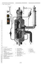
WARNING SIGNALS ON THE CENTRAL
UNIT
The indications of the status and alarm are
signalled by the central unit by means of
the two LEDs situated on the LH side of
the control unit (DV LED and STATUS LED)
1 (Fig.H10/2) and by means of the internal
display with seven segments 2 (Fig.H10/2).
Indications of the operating status
The central unit uses the STATUS and DV
LEDs to indicate the current operating sta-
tus and alarms.
An operating system which acts as follows:
Status red LED On;
the central unit is On
in standby mode (awaiting connection
with the pushbutton panel).
Status green LED On;
the central unit is
On in operating mode (connection made
with the pushbutton panel).
The DV LED is used for indicating the com-
mand output status for safety solenoid
valve (DV).
DEV LED red On;
indicates that the DV
output is active.
Error codes
In case of malfunctioning of the central
unit the fault is indicated by causing the
STATUS LED to flash in red on the internal
display displaying “Er” followed by four
characters divided in two blocks corres-
ponding to the error code found.
Example of error code:
“Er”->”15”->”1A” -> “Er”->”15”->”1A” -> “Er”-
>”15”->”1A”
If the problem found is considered as “tem-
porary”, the error code will be repeated
three times and then the radio control will
return to stand-by, and is turned ON.
On the other hand, if the malfunctioning
is considered as “blocking”, the display will
show the error code continuously until the
radio control switches off.
The error code may appear after the con-
trol unit starts up, after the pushbutton
panel is started up (enabling operating
mode) or after activation of an output.
SEGNALAZIONI DELL’UNITÀ CENTRALE
Le indicazioni di stato e di allarme sono
segnalate dall’unità centrale tramite i due
LED situati sul lato sinistro della centralina
(LED DV e LED STATUS)
1 (fig.H10/2) e attraverso il display interno a
sette segmenti 2 (fig.H10/2).
Indicazioni dello stato operativo
L’unità centrale utilizza i LED STATUS e DV
per indicare lo stato di funzionamento
attuale e gli allarmi.
Un sistema funzionante si comporta come
segue:
LED Status acceso rosso
; l’unità centrale
è accesa in modalità standby (in attesa di
collegamento con la pulsantiera).
LED Status acceso verde
; l’unità centrale è
accesa in modalità operativa (collegamento
con la pulsantiera effettuato).
Il LED DV è usato per indicare lo stato
dell’uscita di comando per l’elettrovalvola
di sicurezza (DV).
LED DV rosso acceso
; indica che l’uscita
DV è attiva.
Codici di errore
In caso di malfunzionamento l’unità centra-
le indicherà l’anomalia facendo lampeggia-
re il LED STATUS in rosso mentre sul display
interno verrà visualizzato “Er”seguito da
quattro caratteri divisi in due blocchi cor-
rispondenti al codice d’errore riscontrato.
Esempio di codice d’errore:
“Er”->”15”->”1A” -> “Er”->”15”->”1A” -> “Er”-
>”15”->”1A”
Se il problema riscontrato è considerato
“temporaneo”, il codice d’errore sarà ripetu-
to tre volte e poi il radiocomando ritornerà
in stand-by, come appena acceso.
Diversamente, se il malfunzionamento è
considerato “bloccante”, il display mostrerà
il codice d’errore continuamente fino a
quando il radiocomando sarà spento.
Il codice di errore può manifestarsi dopo
l’avvio dell’unità centrale, dopo l’avvio della
pulsantiera (abilitazione modalità operati-
va) o dopo l’attivazione di un’uscita.
SIGNALISIERUNG DER ZENTRALEINHEIT
Die Zustandsangaben und
Alarmmeldungen werden der
Zentraleinheit mit den beiden LEDs an der
linken Seite des Steuergeräts (LED DV und
LED STATUS) 1 (Abb. H10/2) und über das
interne Display mit sieben Segmenten 2
(Abb. H10/2) gemeldet.
Angabe des Betriebszustandes
Die Zentraleinheit zeigt mit den LEDs STATUS
und DV den aktuellen Betriebszustand und
die Alarmmeldungen an.
Ein funktionstüchtiges System verhält sich
wie folgt:
LED Status leuchtet rot auf
; die
Zentraleinheit ist eingeschaltet und befin-
det sich im Stand-by-Modus (und wartet
auf die Verbindung mit der Schalttafel).
LED Status leuchtet grün auf
; die
Zentraleinheit ist eingeschaltet und befin-
det sich im Betriebsmodus (Verbindung
mit der Schalttafel wurde aufgebaut).
Die LED DV zeigt den Zustand des
Ausgangs für die Steuerung des
Sicherheitsventils (DV) an.
LED DV leuchtet rot auf
; zeigt an, dass der
Ausgang DV aktiv ist.
Fehlercodes
Bei einer Betriebsstörung der
Zentraleinheit zeigt der Fehlercode die
Anomalie durch das rote Aufblinken der
LED STATUS an, wohingegen auf dem
internen Display die Aufschrift “Er”, gefolgt
von vier in zwei Blöcke unterteilte Zeichen
angezeigt werden, die dem festgestellten
Fehlercode entsprechen.
Beispiel für einen Fehlercode:
“Er”->”15”->”1A” -> “Er”->”15”->”1A” -> “Er”-
>”15”->”1A”
Wenn das festgestellte Problem "vorüber-
gehend" ist, wird der Fehlercode drei Mal
wiederholt und die Funksteuerung geht,j
wie beim Einschalten, in den Stand-by-
Modus über.
Wenn die Betriebsstörung hingegen
eine "Blockierung" auslöst, wird auf dem
Display der Fehlercode angezeigt, bis die
Funksteuerung abgeschaltet wird.
Der Fehlercode kann nach dem Start
der Zentraleinheit, nach dem Start der
Schalttafel (Freigabe des Betriebsmodus)
oder nach der Aktivierung eines Ausgangs
auftreten.
649050
IT-EN-DE
(01/06/2017)
MRT
EASY
55P
400
ST4
S2,
MRT
EASY
55P
360
ST4
S2,
MRT
EASY
75P
400
ST3B
S2,
MRT
EASY
75P
360
ST3B
S2,
MRT-X
EASY
75P
400
ST3A
S2,
MRT-X
EASY
75P
360
ST3A
S2