83
The assembly of the dampers must be carried out while observing all applicable safety standards
and regulations.
If the damper is equipped with limit switches and the said devices are not used during operation
(e.g. because of a project change), they can be left on the damper and not connected (they need
not be dismounted). On the other hand, if a limit switch is to be added to the damper design, the
change can be implemented by adding the required device to the base plate of the damper. The
said facts must be recorded in the respective operation documentation of the damper (record books
of the damper, fire logs, etc.) and subsequently, adequate function checks must be carried out.
For a reliable function of the dampers, their closing mechanism and the seating faces of the blade
must be protected from dust, fibrous or adhesive masses and solvents.
Actuator control without electric voltage:
A special lever (part of the actuator) may be used to manually set the dampers to any position.
When the lever is turned in the direction of the arrow, the damper blade turns to its open position.
As the blade movement is stopped, in every position, the actuator will be locked. Unlocking is
possible even manually as per instructions on the actuator, or by the activation of the supply
voltage.
All flange and screw joints must be conductively connected during the assembly to provide
protection against dangerous contact. 2 fan-shaped washers in galvanized version are to be used
for conductive connection; they are to be situated under the head of one bolt and under the
screwed nut.
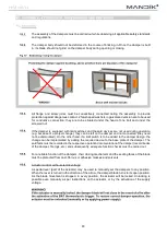
The damper body should not be deformed in the course of bricking in. Once the damper is built
in, its blade should not grind on the damper body during opening or closing.

