9
10
11
12
Removing and installing cylinder head
87
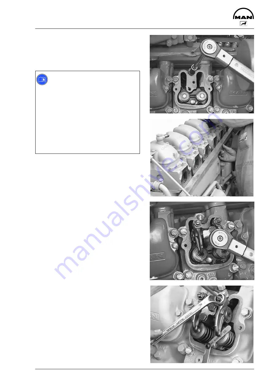
Figs. 9 and 10
Tighten bolts by angle.
Observe tightening sequence, the specified tighte-
ning method, the instructions and notes concerning
the cylinder head bolts.
Note:
To avoid any distortion between cylinder
heads and exhaust manifolds, we recom-
mend proceeding as follows:
D
Place cylinder head gaskets and cylin-
der heads in position
D
Screw in head bolts by a few turns
D
Secure steel ruler (special tool) with
ground face on the exhaust side; tight-
ening torque for mounting bolts: 20 Nm.
If a steel ruler is not available, mount
exhaust manifold and tighten to 20 Nm.
D
Tighten cylinder head bolts as specified
D
Remove steel ruler
Installing the rocker arms and push
rods
Fig. 11
Check push rods for distortion.
When inserting the push rods ensure that they fit
into the seat of the valve tappet.
Put rocker arms and push rods in place.
Tighten the mounting bolts lightly and align the
rocker arms to the valves.
Tighten the mounting bolts to the specified torque.
Fig. 12
Set valve clearance, see page 89.
Mount cylinder head cover with new seal.
D
Installing exhaust manifold
D
Installing intake manifold
D
Fit injection nozzle
D
Fill up with coolant
Summary of Contents for D 2866 LUE 605
Page 1: ......
Page 2: ......
Page 14: ...Notes 12...
Page 19: ...Memoranda 17...
Page 20: ...Engine views 18 Engine views 3 4 2 1 7 6 5 8 11 10 9...
Page 68: ...Memoranda 66...
Page 133: ...131 Service Data...
Page 157: ...155 Special tools...
Page 158: ...Special tools 156 2 3 4 5 6 7 8 1 6 1 6 2 6 3 9 1 9 2 9 3 9...
Page 162: ...Special tools 160 21 22 25 25 2 24 25 1 26 27 1 27 2 27 20 1 19 2 19 1 20 2 19 20 23 28...
Page 164: ...Special tools 162 30 31 32 1 32 32 2...
Page 167: ...Special tools 165 Pressing mandel for cap dia 62 1 mm Pressing mandel for cap dia 50 1 mm...
Page 170: ...Notes 168...
Page 173: ......
Page 174: ......


