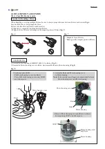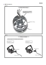
Fig. D-4
W
iring diagram
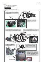
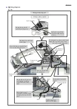
Wiring in Housing set L
Rib A
Sub Controller
Wiring to Sub controller
Switch
Put Lead wires of Switch
in this space.
Route the tube covering the lead
wires on the other lead wires.
Route the lead wires under Noise
suppressor of controller A.
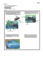
Connector of
switch
Battery fuel
gauge
Noise suppressor
of Controller A
Controller A
Rib B
Put Lead wires of Sub
controller in this groove.
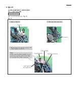
Put the lead wires in this
groove.
Put the closed end
splices in this space.
Put Lead wires of Sub
Controller under the top
of rib A.
Put connectors as shown in the figure.
Note:
Do not put the slacks of the
lead wires on the connectors.
Closed end splice
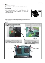
Rib C
Route Lead wires of
Controller A with the closed
end splice between the rib B
and C.
Put the slacks of Lead wires
of Controller A with the
closed end splice in this
space.
P 13/ 13
Summary of Contents for XBU02
Page 1: ...REPAIR MANUAL XBU02...

