background image

P 4/ 13

R

epair

[3] DISASSEMBLY/ASSEEMBLY

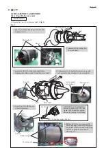
(4) Remove Rotor from Motor housing. (

Fig. 4

)

(5) Remove Motor housing cover and Ball bearings from Rotor. (

Fig. 5

)

Fig. 4

Fig. 5

[3] -1. Fan 110, Rotor (cont.)

DISASSEMBLING


Flat washer 8

Rotor shaft

Rotor

Rotor

Motor housing

Cap

Motor housing cover

1. Remove Flat washer 8 from the rotor shaft.

1. Remove Rotor from Motor housing cover with 1R045.

2. Remove Ball bearings from Rotor using 1R269.

Motor housing

2. Loosen four 3x20 Tapping screws, and  

  disassemble Cap from Motor housing

  so that Rotor can be removed from the 

    cap side.

3. Tap the rotor shaft

  with a plastic hammer.

4. Remove Rotor and Motor housing cover  

  from Motor housing.

Plastic hammer

Motor housing

Rotor

Motor housing cover

1R045


Rotor

Ball bearing 626DDW

1R269

Rotor

Motor housing

cover

Ball bearing

698LLU

Ball bearing

698LLU

Ball bearing

626DDW

Summary of Contents for XBU02

Page 1: ...REPAIR MANUAL XBU02...

Page 2: ...for arbor 20 100 press fitting Rotor and Motor housing cover 1R269 Bearing extractor removing Ball bearing 626DDW 698LLU from Rotor No need to lubricate Repair 3 DISASSEMBLY ASSEEMBLY 1 Remove Front...

Page 3: ...ng hex nut from the rotor shaft by turning it counterclockwise with the impact driver 4 Fan 110 can be removed using 1R045 if it is difficult to remove by hand 3 1 Fan 110 Rotor cont DISASSEMBLING Swi...

Page 4: ...1 Remove Rotor from Motor housing cover with 1R045 2 Remove Ball bearings from Rotor using 1R269 Motor housing 2 Loosen four 3x20 Tapping screws and disassemble Cap from Motor housing so that Rotor ca...

Page 5: ...net portion of Rotor 1 Assemble Ball bearings 626DDW 698LLU to Rotor Fig 5 2 Assemble Motor housing cover to Rotor And assemble them to Motor housing Fig 8 ASSEMBLING Fig 8 Rotor Rotor Stator 1R032 1R...

Page 6: ...e rail assemble Flat washer 5 to the rotor shaft 2 Assemble Flat washer 8 to the rotor shaft Socket bit 8 55 Rubber ring 8 Housing set L 4 Lock Fan 110 with the grip of plastic hammer 5 Attach M5 Cone...

Page 7: ...aligning their protrusions on Lock ON buttons in the same direction If not Housing set R may not be fixed properly 2 Assemble Lock ON button to Housing set L while fitting one protrusion to the cut p...

Page 8: ...Sub controller Connector Axis for Dial 28 Lead wires of Sub controller 1 Remove Dial 28 2 Disconnect the connector 3 Remove Sub controller by prying it off with a slotted screwdriver Slotted screwdriv...

Page 9: ...h lever Note in Repairing Star mark Fig T 1 Fig T 2 Test for recognizing the trouble on FET Field effect transistor of Controller 2 After removing the battery from the machine lock Switch lever to ON...

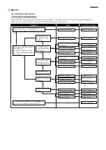
Page 10: ...te connection Connectors are in incomplete connection The machine does not have any trouble Check Lead wires or replace them Check Terminal or replace it Check Lead wires or replace them Battery fuel...

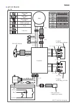
Page 11: ...Purple Red White Yellow 26AWG 26AWG 28AWG 28AWG 28AWG 24AWG Battery fuel gauge Terminal on Housing set R side Terminal on Housing set L side Sub controller for variable speed control Red 5 White 1 Gra...

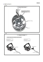
Page 12: ...de Terminal of Housing set L side Stator Motor housing Wiring to Terminals Flag connector Led wire red Led wire blue Flag connector Route Lead wires of Startor through this groove Wiring in Motor hous...

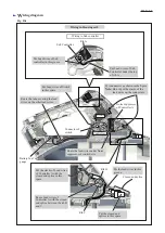
Page 13: ...of Controller A Controller A Rib B Put Lead wires of Sub controller in this groove Put the lead wires in this groove Put the closed end splices in this space Put Lead wires of Sub Controller under th...

Reviews: