background image

R

epair

[4] DISASSEMBLY/ASSEMBLY

[4]-14. Engine block (cont.)

(1) Piston can be assembled in either direction.

     Apply Makita grease N No. 2 to the needle bearing of Crank shaft assembly in advance.

(2) Insert Piston pin through Piston and Crank shaft, and fix it with Clips by using an awl (Clip has no direction). 

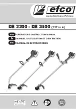
(3) Piston rings have their directions and each different shapes as drawn in 

Fig. 60

.

      First, install Piston ring 34, and next, install Piston ring (second) 34, then finally install Piston ring (top) 34.

      The piston ring 34 (fast one) consists of three part ; top ring, middle ring and bottom ring.

      Top ring and bottom ring have a clearance and the distance of each clearance point must have 120° angle.

      Piston ring (top) 34 and Piston ring (second) 34 consist of single part and the distance between their clearances

      must have 180° angle when they fixed into the grooves on the piston. 


Note

: Piston rings are easy to break. Do not enlarge them too much when fixed.

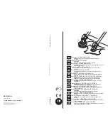
(4) Assemble Cylinder block assembly.

     Degrease the matching surface of Cylinder block and Crank case (Refer to 

Fig. 61

), apply ThreeBond 1216

     on the Crank case side.


Note

: The layer of ThreeBond 1216 has to be thin so as not to enter into the oil route in Engine and get clogged. 

     Apply 4stroke oil to the contact surface of Piston and Cylinder.

     While holding Piston rings, Install the assembled part of Piston into Cylinder block.

(5) Fasten Cylinder block assembly by tighten the screws in crisscross pattern.

Fig. 60

P 1

3

/ 1

4


Fig. 61

ASSEMBLING

Piston ring (top) 34

Piston ring (top) 34

The center is expanded.

Piston top end

Bottom layer

Middle layer

Top layer

The matching surface: emphasized by black color

Piston ring (second) 34

The bottom is wider than the top.

The position between two 

clearances must be

at 180° opposite point.

Difference of the clearance

should be 

120°.

Cross section of Piston

Piston ring (second) 34

Piston ring 34

Piston ring 34

consists of three layers. 

The top layer and the bottom layer have a clearance

as drawn above. 

Clearances should not be overlapped each other.

Piston

Summary of Contents for EM2650UH

Page 1: ...ess Note The standard equipment for the tool shown above may vary by country Cutting tool 1 Universal guard Protector 1 Shoulder harness with double shoulder straps 1 for EM2650UH EM2651UH Shoulder ha...

Page 2: ...ring R 24 Retaining ring pliers ST 2 for Internal ring Pressfitting Spiral bevel gear 14 the component of Cutter shaft set Bearing setting pipe 20 12 2 1R028 1R006 1R004 When Gasket is removed 1 clea...

Page 3: ...pliers to pull out the shaft Fig 4 Take the disassembling step in reverse Set Control cable in place Figs 2 and 6 Secure it on the projection of Insulator with two Nuts of Control cable Fit the hook...

Page 4: ...11 7 According to the clause of 4 2 Remove Shaft pipe complete 8 Remove Hanger and Shaft from Shaft pipe complete Fig 12 Assemble in the reverse order of disassembly Slip Hanger on Shaft pipe complete...

Page 5: ...ut to Cutter shaft as drawn in Fig 19 and give the impacts using the plastic hammer An assembled part of Cutter shaft complete Ball bearing 6001LLU is removed Refer to Fig 20 for the components 9 Remo...

Page 6: ...section 3 Remove Clutch drum from Clutch case section with Arbor press Fig 26 1 Put Clutch case on the table of Arbor press vertically then pressfit Clutch drum into Ball bearing 6201LLU with 1R286 an...

Page 7: ...plug carefully 4 Install Plug cap with Plug cap spring on Plug and connect the plug screw part to a metal part of Engine then pull Starter rope slowly The sparks can be seen when starter rope is pulle...

Page 8: ...Fig 34 instead of M6x25 shoulder hex bolts Flywheel is removed from Engine Important Screw two M6 bolts evenly ASSEMBLING 1 Wipe off the grease and oil from Crank shaft Fig 35 2 Put Woodruff key 3 int...

Page 9: ...g 40 how to make a knot of the rope 4 Wind the rope two or three turns 5 While turning Reel counterclockwise fit it into Starter case and hook Spiral spring end on the rib inside of Starter case Fig 4...

Page 10: ...rn out Fig 48 5 When Control lever is set in place make sure that Spring is put properly as drawn in Fig 49 6 Regarding three M3x8 Pan head screws with washers loosen Idling screw fully first and then...

Page 11: ...ot touch on Cylinder cover 3 Set Air cleaner elements in place The felt element is put on the bottom and the sponge element is on the front 4 Hook the tabs of Cleaner plate assembly with the holes of...

Page 12: ...to screw them 6 Set Cylinder cover in place 1 Drain the oil from Engine as much as possible so that the remaining oil is not spilled out when disassembling 2 Remove the following parts from Engine Cyl...

Page 13: ...ge them too much when fixed 4 Assemble Cylinder block assembly Degrease the matching surface of Cylinder block and Crank case Refer to Fig 61 apply ThreeBond 1216 on the Crank case side Note The layer...

Page 14: ...T M5 16 CLUTCH BOLT M6 25 HEX SOCKET HEAD BOLT M5 40 W MEC M10 P1 0 HEX SOCKET HEAD BOLT M5 18 W SW HEX SOCKET HEAD BOLT M5 18 W SW M8 HEX SOCKET HEAD BOLT M5 16 W SW HEX SOCKET HEAD BOLT M5 14 W SW H...

Reviews: